
User Manual
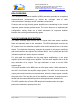

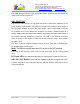
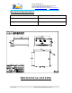
Table Of Contents

Dekolink WIRELESS Ltd.
16 Bazel St. Qiryat-Arieh Petah-Tikva, Israel, 49510
Tel- 972-3-9180-180 Fax-972-3- 190-9180
e-mail: marketing@decolink.com
web www.decolink.com
Duplexe
r
Downlink
Duplexe
r
Uplink
LNA
Filter Attenuator
Power
Monitor
PA
AGC
LNA
Attenuator Filter
Power
Monitor
PA
AGC
BDA RF BLOCK DIAGRAM
TO
BASE
TO
MOBILE
BDA OPERATION
The RF connection is made via two type “N” female connectors. The RF
connector labeled “Base” should be connected to the antenna pointing to the
base station; usually a rooftop antenna. The RF connection labeled “Mobile”
should be connected to the antenna pointing into the area to be covered by the
BDA; such as inside a building.
Step Attenuator & RF Gain Setting
For proper operation of the BDA; the isolation between the base station antenna
and the mobile antenna should exceed the BDA gain by at least 12 dB. If the
BDA gain is higher than the isolation between the antennas, oscillation would
start and would saturate the amplifier. Isolation of few dB higher than the BDA
gain cannot start oscillations but would cause gain ripple in the band.
The step attenuator on the low noise amplifier can reduce the BDA gain.
By using
the rotary knob , the attenuation can be adjusted in 2 dB
steps up to 30 dB.
Page
4 of
8
CBDA-PCSAC-10W80 INST-FCC.doc