
User's Manual
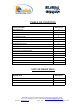
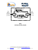
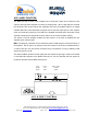
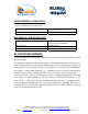
Table Of Contents
- BDA
- RF BLOCK DIAGRAM
- The switch on the RF amplifier enables the AGC function. If the AGC is disabled then the amplifier gives maximum gain.
- MGC: The RF gain of the BDA can be reduced by about 15 dB using the continuos trimmer on the amplifier. The RF gain is at maximum when the trimmer is at counter-clockwise direction. To reduce the gain, turn the trimmer clockwise using a screwdriver. Turn
- The AGC and MGC functions for the uplink path are reached by opening a small cover located on the DBA side adjacent to the Mobile antenna port. For the downlink path the window is located on the side near the Base antenna port.
- Limited Warranty
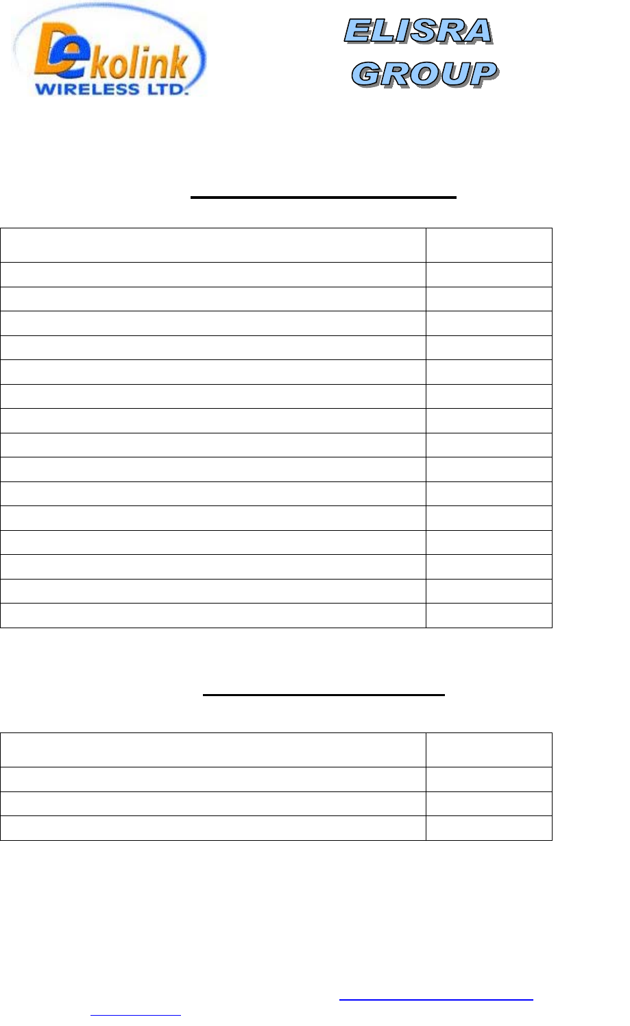
TABLE OF CONTENTS
PARAGRAPH PAGE No
BDA OVERVIEW 3
BLOCK DAIGRAM DESCRIPTION 3
AGC & MGC FUNCTION 5
BDA INSTALLATION 6
BASE/DONOR ANTENNA INSTALLATION 6
REMOTE/SERVICE ANTENNA INSTALLATION 6
ANTENNA ISOLATION 6
INSTALLATION STEPS 7
DIAGNOSTICS GUIDE 8
ELECTRICAL SPECIFICATIONS 9
SYSTEM FREQUENCY RANGE 9
ENVIRONMENTAL CONDITIONS 10
MECHANICAL SPECIFICATIONS 10
RF EXPOSURE WARNING 10
DEKOLINK WIRELESS LIMITED WARRANTY 12
LIST OF DRAWINGS
DRAWING PAGE No
BDA (WITH AGC) RF BLOCK DIAGRAM DRAWING 4
AGC & MGC CONTROL 5
MECHANICAL OUTLINE 11
Dekolink Wireless Ltd.;16 Bazel St.Qiryat-Arieh Petah-Tikva Israel, 49510
Tel- 972-3-9180-180; Fax-972-3- 190-9180 ; Email-marketing@dekolink.com
;
Web site-
www.dekolink.com
r
ev 8
10/03
page 2 of 12