
Installation Manual

Dekolink Wireless Ltd.;16 Bazel St.Qiryat-Arieh Petah-Tikva Israel, 49510
Tel- 972-3-9180-180; Fax-972-3- 190-9180 ;
Email-marketing@dekolink.com
;
Web site-
www.dekolink.com
r
ev 5 11/
02
page 5 of 12
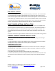
AGC FUNCTION
The BDA has AGC function on both paths that serve to prevent the saturation of the
power amplifier. Their amplifier has a directional coupler and a detector at the output of
the high power amplifier to monitor the output power. When a high signal is received
the automatic level control detects the amplitude and sends a feedback signal to a
voltage variable attenuator which attenuates the signal level so that the output power of
the amplifier does not exceed the preset limit. The LED on the amplifier illuminates
when the power out the amplifier is within the set limit (when the AGC is On and when
the AGC is OFF).
The switch on the RF amplifier enables the AGC function. If the AGC is disabled then
the amplifier gives maximum gain.
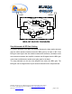
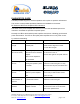
AGC AND GAIN CONTROLS
The AGC and GAIN SETTING functions for the up link path are reached by opening the
small slide door located on the CBDA left side, adjacent to the BASE antenna port. For
the down link path the door is on the right side adjacent to the MOBILE antenna port
RF Power LED
:
The LED illuminates when the output power exceeds the AGC Set .
AGC ON / OFF Switch
:
When OFF the amplifier works with its highest gain (AGC
Function OFF). When set to ON (AGC Function ON) the amplifier power output cannot
exceed the set limit.
Gain setting:
By using the rotary knob , the attenuation can be adjusted in 2 dB
steps.