
Installation and Operating Instructions
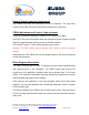
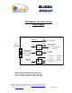
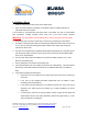
Table Of Contents

Dekolink Wireless Ltd.;16 Bazel St.Qiryat-Arieh Petah-Tikva Israel, 49510
Tel- 972-3-9180-180; Fax-972-3- 190-9180 ;
Email-marketing@dekolink.com
Downlink
Uplink
LNA
Attenuator
Power
Monitor
PA
AGC
LNA
Attenuator
PA
AGC
To Base
To Service
Area
TX
806 to
821 MHz
896 to
902 MHz
851 to
866 MHz
935 to
941 MHz
RX
Quad Filter
Assy
TX
806 to
821 MHz
896 to
902 MHz
851 to
866 MHz
935 to
941 MHz
RX
Quad Filter
Assy
Power
Monitor
RF Block Diagram
Step Attenuator & RF Gain Setting
For proper operation of the CBDA; the isolation between the base station
antenna and the mobile antenna should exceed the CBDA gain by at least 12
dB. If the CBDA gain were higher than the isolation between the antennas,
oscillation would start and would saturate the amplifier. Isolation few dB higher
than the CBDA gain cannot start oscillations but would cause gain ripple in the
band.
The step attenuator on the low noise amplifier can reduce the CBDA gain. The
CBDA gain can be stepped down by the amount indicated on the step attenuator
(
0 to 30 dB in 2 dB steps).
;
Web site- www.dekolink.com rev 1 11/04 page 5 of 16