
Installation and Operating Instructions
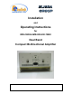
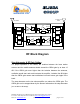
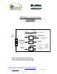
Table Of Contents

Dekolink Wireless Ltd.;16 Bazel St.Qiryat-Arieh Petah-Tikva Israel, 49510
Tel- 972-3-9180-180; Fax-972-3- 190-9180 ;
Email-marketing@dekolink.com
Remote Alarm Connector (back panel)
Dry contact relay arms are connected to this D9 connector. The relay arms
switch over at either one of the two alarms indicated on the top cover.
)dowsside win(CBDA Indications and Control
These are reached by opening the window on the sides of the CBDA
AGC LED: This red led illuminates when the transmitted power is equal or higher
than the composite power (factory preset at +24 dBm and DL).
AGC ON/OFF switch: Turns on the automatic power control.
Warning: The AGC switch must be always ON in order to limit the spurious
signals.
Step attenuator: The CBDA gain can be stepped down by the amount indicated
on the step attenuator.
lock Diagram DescriptionB
The CBDA Downlink path receives TX signals from base station amplifies them
and transmits them to the subscriber. The CBDA Uplink path receives RX
signals from the subscriber amplifies them and transmits them to the base
station. Two quad filter assemblies frequency separate the signals to the proper
amplifying path and isolate the two signals.
Each path has two amplifiers; a low noise amplifier (LNA) and a high power
amplifier. The low noise amplifier has a 30 dB step attenuator, which is used to
set the repeater gain.
The power amplifiers in the CBDA have an AGC option switch. They also have a
Power LED lamp that illuminates when the output power has reached the preset
power limit.
;
Web site- www.dekolink.com rev 1 11/04 page 4 of 16