
Installation and Operating Instructions
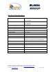
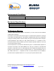
Table Of Contents

Dekolink Wireless Ltd.;16 Bazel St.Qiryat-Arieh Petah-Tikva Israel, 49510
Tel- 972-3-9180-180; Fax-972-3- 190-9180 ;
Email-marketing@dekolink.com
Electrical Specifications
Downlink frequency range 851- 869 MHz
935 - 941 MHz
Uplink frequency range 806 - 824 MHz
896 - 902 MHz
Pass band gain @min attenuation 80 dB nominal
Pass band ripple
± 2 dB typical
Manual attenuation range 0 to 30 dB in 2 dB step
Noise figure @max gain 6.0 dB max
V.S.W.R In/Out 1.5: 1 max
AGC selection By ON/OFF Switch
AGC attenuation range 25 dB typical
AGC LED indication LED turn ON when power reaches AGC Set
Power Level. (both at On and Off positions).
Composite power +25 dBm nom.
AGC factory power preset +24 dBm nom.
3rd Order output spurious 48 dBc typical for 2 signals +20 dBm each
3rd Order output Intercept point +44 dBm typical
Downlink alarm turn on DL power <15 dBm
Power Supply 110/220V AC, 50-60 Hz /50 Watt
;
Web site- www.dekolink.com rev 1 11/04 page 13 of 16