
Installation and Operating Instructions
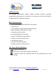
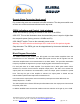
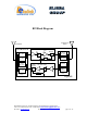
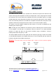
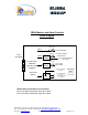
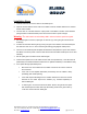
Table Of Contents
- and
- Dual Band
- Compact Bi-Directional Amplifiers
- The switch on the RF amplifier enables the AGC function. If the AGC is disabled then the amplifier gives maximum gain.
- MGC: The RF gain of the CBDA can be reduced by about 15 dB using the continuos trimmer on the amplifier. The RF gain is at maximum when the trimmer is at counter-clockwise direction. To reduce the gain, turn the trimmer clockwise using a screwdriver. Tur
- The AGC and MGC functions for the uplink path are reached by opening a small cover located on the DBA side adjacent to the Mobile antenna port. For the downlink path the window is located on the side near the Base antenna port.
- Limited Warranty

RF Block Diagram
Downlink
Uplink
Attenuator
Power
Monitor
PA
AGC
Attenuator
PA
AGC
To Base
To Service
Area
TX
806 to
824 MHz
896 to
902 MHz
851 to
869 MHz
935 to
941 MHz
RX
Quad Filter
Assy
TX
806 to
824 MHz
896 to
902 MHz
851 to
869 MHz
935 to
941 MHz
RX
Quad Filter
Assy
Power
Monitor
Gain Control
Gain Control
Dekolink Wireless Ltd.;16 Bazel St.Qiryat-Arieh Petah-Tikva Israel, 49510
Tel- 972-3-9180-180; Fax-972-3- 190-9180 ; Email-marketing@dekolink.com
;
Web site-
www.dekolink.com rev 0 11/04 page 5 of 16