
Installation and Operating Instructions
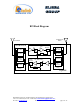
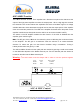
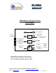
Table Of Contents
- and
- Dual Band
- Compact Bi-Directional Amplifiers
- The switch on the RF amplifier enables the AGC function. If the AGC is disabled then the amplifier gives maximum gain.
- MGC: The RF gain of the CBDA can be reduced by about 15 dB using the continuos trimmer on the amplifier. The RF gain is at maximum when the trimmer is at counter-clockwise direction. To reduce the gain, turn the trimmer clockwise using a screwdriver. Tur
- The AGC and MGC functions for the uplink path are reached by opening a small cover located on the DBA side adjacent to the Mobile antenna port. For the downlink path the window is located on the side near the Base antenna port.
- Limited Warranty

Remote Alarm Connector (back panel)
Dry contact relay arms are connected to this D9 connector. The relay arms switch over
at either one of the two alarms indicated on the top cover.
)side windows(CBDA Indications and Control
These are reached by opening the window on the sides of the CBDA
AGC LED: This red led illuminates when the transmitted power is equal or higher than
the composite power (factory preset at +24 dBm and DL).
AGC ON/OFF switch: Turns on the automatic power control.
Warning: The AGC switch must be always ON in order to limit the spurious signals.
Step attenuator: The CBDA gain can be stepped down by the amount indicated on the
step attenuator.
Block Diagram Description
The CBDA Downlink path receives the RF signals from base station amplifies them and
transmits them to the subscriber. The BDA Uplink path receives the RF signals from the
subscriber amplifies them and transmits them to the base station. Two quad filter assemblies
frequency separate the signals to the proper amplifying path and isolate the two signals.
For each path there is an AGC amplifier. The amplifier has an AGC option switch. When
switched on, the AGC circuit limits the amplifier output power. The AGC circuit senses the
output power and introduces more attenuation, when the output power exceeds the preset
level. This way the gain of the amplifier is reduced, its output power is limited and the
intermodulation products are kept below the desired level.
In this manner the output power cannot exceed the preset power and the IMD levels are
always kept below –13 dBm.
The AGC amplifier has a Power LED lamp that illuminates when the output power has reached
the preset power limit.
In addition the BDA has a trimmer that enables continuos reduction of the gain by over 15 dB.
Dekolink Wireless Ltd.;16 Bazel St.Qiryat-Arieh Petah-Tikva Israel, 49510
Tel- 972-3-9180-180; Fax-972-3- 190-9180 ; Email-marketing@dekolink.com
;
Web site-
www.dekolink.com rev 0 11/04 page 4 of 16