
Installation and Operating Instructions
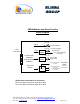
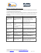
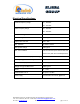
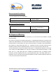
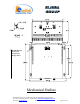
Table Of Contents
- and
- Dual Band
- Compact Bi-Directional Amplifiers
- The switch on the RF amplifier enables the AGC function. If the AGC is disabled then the amplifier gives maximum gain.
- MGC: The RF gain of the CBDA can be reduced by about 15 dB using the continuos trimmer on the amplifier. The RF gain is at maximum when the trimmer is at counter-clockwise direction. To reduce the gain, turn the trimmer clockwise using a screwdriver. Tur
- The AGC and MGC functions for the uplink path are reached by opening a small cover located on the DBA side adjacent to the Mobile antenna port. For the downlink path the window is located on the side near the Base antenna port.
- Limited Warranty

RF Power Amplifiers LED Indications
The LEDs on the power amplifier are set to turn on when the transmitted power has reached
or exceeded the specified composite power.
Normally the LED at the downlink power amplifier should be on indicating good forward power
transmission. The LED on the uplink power amplifier turns on only when a near by mobile is
transmitting.
Indication Cause Action
Downlink LED (on
amplifier) does not
light
Indicates low RF power at
downlink path (below AGC
setting)
Check base antenna connection
Check antenna alignment to base.
Increase CBDA RF gain.
Downlink LED (on
amplifier) lights
(This is not a fault)
Indicates good power
transmission in the downlink
amplifier.
Make sure the amplifier is
not overloaded
Turn AGC on, or reduce gain so that LED
just turns from off to on.
Set the same gain for the uplink channel
Uplink LED (on
amplifier) lights all
the time
Bad antenna isolation
causing the repeater system
to oscillate
Improve the isolation between the
antennas or reduce RF gain. To verify
disconnect one RF port; LED should turn
off
Uplink LED (on
amplifier) lights all
the time
Faulty system. Can be quad
filter assembly or power
amplifier fault
System fault. To verify disconnect one RF
port to verify. If LED remains on then
system is faulty.
Excessive
intermodulation or
spurious
Amplifier oscillation caused
by insufficient isolation
Improve the isolation between the
antennas or reduce RF gain.
Excessive noise in
downlink
High input power causing
amplifier overload
Turn AGC on, or reduce gain so that LED
just turns from off to on. Set the same
gain for the uplink channel
Dekolink Wireless Ltd.;16 Bazel St.Qiryat-Arieh Petah-Tikva Israel, 49510
Tel- 972-3-9180-180; Fax-972-3- 190-9180 ; Email-marketing@dekolink.com
;
Web site-
www.dekolink.com rev 0 11/04 page 12 of 16