
Installation and Operating Instructions
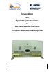
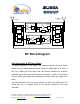

Table Of Contents

Dekolink Wireless Ltd.;16 Bazel St.Qiryat-Arieh Petah-Tikva Israel, 49510
Tel- 972-3-9180-180; Fax-972-3- 190-9180 ;
Email-marketing@dekolink.com
CBDA Monitor and Alarm
The two main active elements are the Downlink Power Amplifier and the Uplink power
amplifier. Each CBDA has a monitor circuit to monitor these elements and give alarm
signal when there is a deviation from normal operation. The summarized alarm output of
the monitor card is sent to a D-type connector on the front panel.
The monitor circuit performs the following functions:
• Monitors the current of uplink power amplifier. If the current is below or above the
specified limits then an automatic alarm function is provided by a LED which
turns on and by dry contacts of a relay.
• Monitors the downlink RF output power. If the output power is over 8 dB below the
rated value then an alarm function is provided by a LED which goes on and by
dry contacts of a relay.
• The relay arms are normally open, they close when power goes on . Whenever
any fault occurs or when the power is cut off from the CBDA the relay arms
open. The relay arms are connected to pins 2,4 of a 9 pin D type male connector
on the front panel of the CBDA for remote sensing of faults.
Pin 2 and 3 of the D type connector provide complimentary relay alarm function;
short at fault and open at no fault.
• The alarm LEDs (red) are displayed on the CBDA cover. The green led is power
on indication.
;
Web site- www.dekolink.com rev 0 08/04 page 7 of 16