
Installation and Operating Instructions
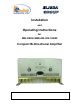

Table Of Contents

Dekolink Wireless Ltd.;16 Bazel St.Qiryat-Arieh Petah-Tikva Israel, 49510
Tel- 972-3-9180-180; Fax-972-3- 190-9180 ;
Email-marketing@dekolink.com
ain CharacteristicsM
• Covers both SMR 800 and SMR 900 in one product.
• 80 dB RF gain
• Over 32 dBm (1.5 Watt) downlink composite power.
• Alarm indication by LED and Dry contact
• Automatic power limit option
Top cover alarm indications
PWR: Power on green LED
UL: Illuminates at uplink power amplifier current fault
DL:
Downlink RF power fault. Illuminates when the DL transmitted power is
less than +20 dBm.
Remote alarm connector (Front panel)
Dry contact relay arms are connected to this D9 connector. The relay arms
switch over at either one of the alarms indicated on the top cover.
)on side windows(CBDA indications and control
These are reached by opening the window on the sides of the CBDA
AGC LED: This red led illuminates when the transmitted power is higher than
the composite power (factory preset at +31 dBm for DL and +24 dBm for UL).
AGC ON/OFF switch
: Turns on the automatic power control.
Warning:
The AGC switch must be always ON in order to limit the spurious
signals.
Step attenuator: The CBDA gain can be stepped down by the amount
indicated on the step attenuator.
;
Web site- www.dekolink.com rev 0 08/04 page 3 of 16