
Installation and Operating Instructions

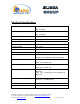
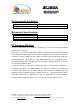
Table Of Contents

Dekolink Wireless Ltd.;16 Bazel St.Qiryat-Arieh Petah-Tikva Israel, 49510
Tel- 972-3-9180-180; Fax-972-3- 190-9180 ;
Email-marketing@dekolink.com
Electrical Specifications
Downlink frequency range 851- 869 MHz
935 - 941 MHz
Uplink frequency range 806 - 824 MHz
896 - 902 MHz
Pass band gain @min attenuation 80 dB nominal
Pass band ripple
± 2 dB typical
Manual attenuation range 0 to 30 dB in 2 dB step
Noise figure @max gain 6.0 dB max
V.S.W.R In/Out 1.5 : 1 max
AGC selection By ON/OFF Switch
AGC attenuation range 25 dB typical
AGC LED indication LED turn ON when power reaches AGC Set
Power Level. (both at On and Off positions).
Composite power Up link: +25 dBm nom.
Down link: +32 dBm nom.
AGC factory power preset Up link: +24 dBm nom.
Down link: +31 dBm nom.
3rd Order output spurious Up Link : 48 dBc typical for 2 signals +20
dBm each
Down Link : 45 dBc typical for 2 signals +28
dBm each
3rd Order output Intercept point Up Link : +44 dBm typical
Down Link :+51 dBm typical
Downlink alarm turn on DL power <20 dBm
Power Supply 110/220V AC, 50-60 Hz /100 Watt
;
Web site- www.dekolink.com rev 0 08/04 page 13 of 16