
User's Manual

D
EKOLINK
W
IRELESS
L
TD
.
C
OMPACT
B
I
-D
IRECTIONAL
A
MPLIFIER
D
EKO
3178B
P
RODUCT
M
ANUAL
Pub. 300TC80031 Rev. 1.55 Proprietary Data Page 15
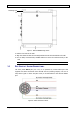
The following table provides a description of the Alarm connector pinout and the
corresponding cable wire color-match pin.
No.
Pin
Signal Name
1 A Not Connected
2 B Not Connected
3 C Dry Contact – Normally Closed
4 D Dry Contact - Normally Open
5 E Not Connected
6 F Not Connected
7 G Dry Contact - Common
• The relay alarms are
Normally Open
, however they close upon power up. Upon
detecting a fault or when the power is cut off from the CBDA the relay alarms open.
• The relay alarms are connected to pins 3 and 4 of the front panel Alarms connector
used for remote sensing of faults.
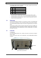
3.4 G
ROUNDING
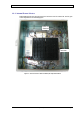
Once the Dual Band BDA is installed, you are required to ground it. The Dual Band BDA
case includes a grounding lug, where a grounding conductor cable should be attached.
The Dual Band BDA grounding conductor is found at the right-hand side of the bottom
panel.
The protective grounding conductor should be copper with cross-section of 10AWG. The
lug of the protective conductor should also be aluminum. Washers and screw should be
high CR stainless steel, or 12% stainless steel, or 12% Cr stainless steel, or Cr on steel,
Ni on steel, tin on steel.
3.5 P
OWER
U
P
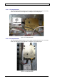
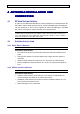
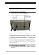
To power-up
The Dual Band BDA operates from a 100/240 VAC Mains. The maximum consumption
power is 105W.
Connect the AC power cable to the Dual Band BDA front panel AC IN (100-240VAC)
connector.
Figure 9.Power Up Connection
100-240VAC