
User Manual
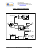
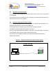
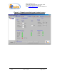
Table Of Contents

Dekolink WIRELESS Ltd.
16 Bazel St. Qiryat-Arieh Petah-Tikva, Israel, 49510
Tel- 972-3-9180-180 Fax-972-3- 190-9180
e-mail: marketing@dekolink.com
web www.dekolink.com
50W rev 1 10/03 Page 8 of 16
4. Repeater monitoring and control
4.1. Controls
4.1.1. PAmp On: Turns on/off the downlink power amplifier (
√
indicates amplifier is
on)
4.1.2. Max Power:
This window is blank when the downlink ALC is turned off (
√
indicates DL ALC is on)
4.1.3. Max Gain:
The repeater gain is selected from a choice list
4.1.4. FWD Threshold:
This value sets the lower limit for a downlink power alarm
declaration. For example if the value shows 33dBm and the repeater transmits
less than 33dBm (downlink), the FWD Measure alarm (that appears in the Link
Alarm Status) will turn red. The actual transmitted power is also shown.
4.2. Link alarm status (downlink & uplink)
4.2.1. Power Amplifier: Turns red when the Power Amplifier (PA) current is above
or below its specified limits
4.2.2. Main Voltage:
Turns red when the internal power supply voltage is below or
above its limits
4.2.3. Pre Amplifier:
Turns red when the Low Noise Amplifier (LNA) current is
above or below its specified limits
4.2.4. VSWR:
Turns red when the return loss of the downlink antenna or cable
connection exceeds 10dB (=VSWR 2:1)
4.2.5. FWD Measure:
see FWD Threshold above
4.3. General alarm status
4.3.1. Temperature: Turns red when the chassis temperature exceeds 80
°
C
4.3.2. Door Open: Turns red when the repeater’s door is opened
4.3.3. FAN Failure:
Turns red when the internal FAN current is above or below its
specified limits