
User Manual
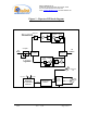
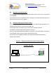
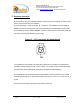
Table Of Contents
Dekolink WIRELESS Ltd.
16 Bazel St. Qiryat-Arieh Petah-Tikva, Israel, 49510
Tel- 972-3-9180-180 Fax-972-3- 190-9180
e-mail: marketing@dekolink.com
web www.dekolink.com
50W rev 1 10/03 Page 7 of 16
3.
Repeater operation
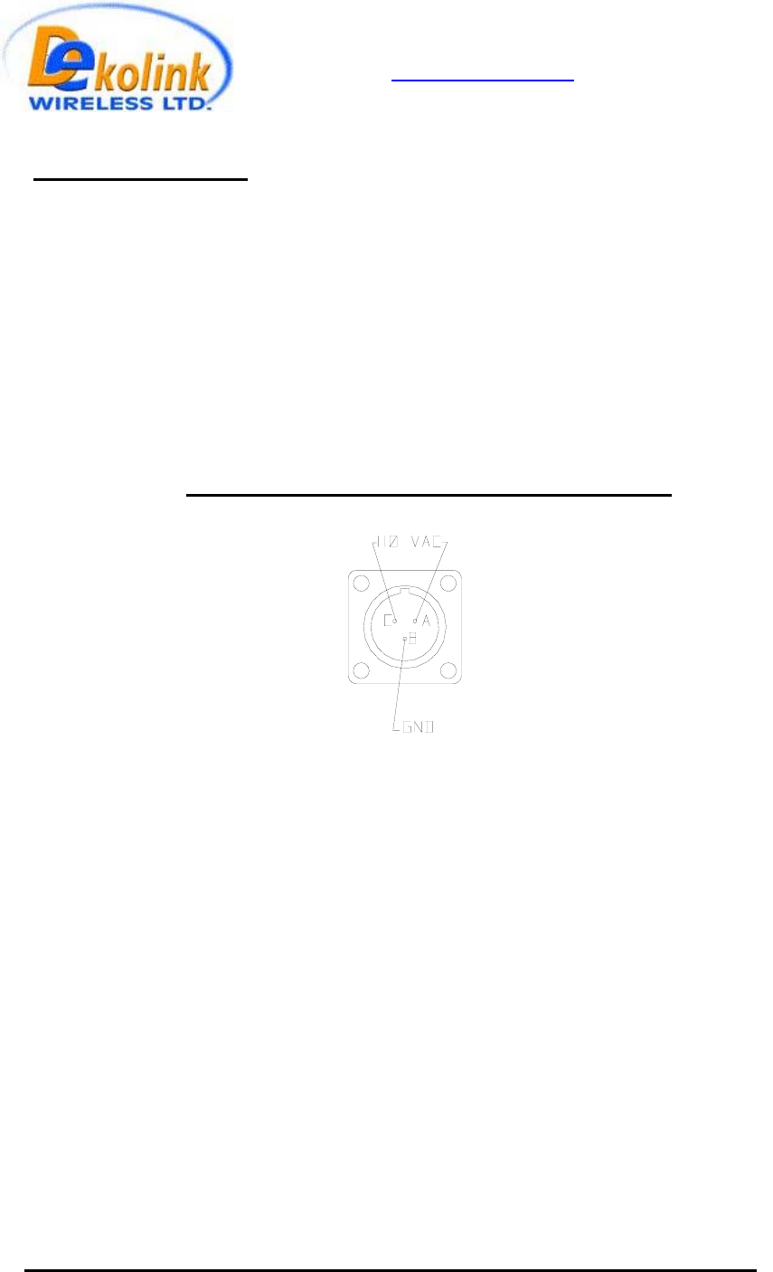
The repeater AC power is supplied through a 3-wire male plug connector. A switch on the
power control unit turns on the repeater.
The RF connection is made via 2 type “N” connectors. The repeater connector labeled
“BASE” must be connected to the roof antenna pointing to the base station (donor side).
The repeater connector labeled “MOBILE” must be connected to the antenna/s pointing to
the area covered by the repeater (service side).
Figure 3 – AC connector pin assignment
The repeater can be remotely controlled and monitored via a modem connected to the
repeaters’ remote monitoring and control module. The modem uses a directional coupler
to transmit and receive RF signals through the repeater base side antenna.
The repeater can be controlled locally through RS232 connector housed on the remote
monitoring and control unit. This is a D9 male connector; pin 2 is Tx; pin 3 is Rx and pin 5
is Gnd.
The power on/off switch is housed on the power control unit.