
User Manual
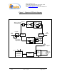
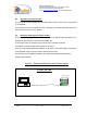
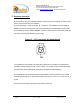
Table Of Contents

Dekolink WIRELESS Ltd.
16 Bazel St. Qiryat-Arieh Petah-Tikva, Israel, 49510
Tel- 972-3-9180-180 Fax-972-3- 190-9180
e-mail: marketing@dekolink.com
web www.dekolink.com
50W rev 1 10/03 Page 3 of 16
1. Repeater overview
Dekolink’s repeater assembly provides an exceptional capability to extend the coverage
area of radio communications into building areas and RF shielded environments.
The unit’s integrated high linearity power amplifiers contribute to the overall improved
system performance while avoiding non-linear related phenomena. The unit is based on a
duplexed path configuration, having sharp out of band attenuation for improved isolation
between the receiving and transmitting paths.
2. Block diagram description
Within the repeater, the downlink path receives RF signals from base station (donor side)
amplifies them and re-transmits them to the subscribers (service area). The repeater
uplink path receives RF signals from the service side, amplifies them and retransmits
them towards the donating base station. On both the repeaters’ ends, cavity tuned
duplexers separate the Tx and Rx signals (frequency separation) and diverts them to the
amplifying path while providing the required signal isolation.
Two amplifiers are used to perform the required amplification for each of the paths; a Low
Noise Amplifier (LNA) and a high power amplifier. Each of the LNAs includes an internal
step attenuator that allows adjusting the gain of the relevant path to the required level
depending on the specific field situation.