
User Manual
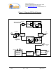
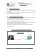
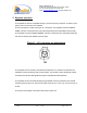
Table Of Contents

Dekolink WIRELESS Ltd.
16 Bazel St. Qiryat-Arieh Petah-Tikva, Israel, 49510
Tel- 972-3-9180-180 Fax-972-3- 190-9180
e-mail: marketing@dekolink.com
web www.dekolink.com
50W rev 1 10/03 Page 5 of 16
2.1. Step attenuator and RF gain setting
For proper operation and in order to avoid oscillations, Dekolink’s suggestion is to have
an isolation value between the base station antenna (donor side) and the mobile antenna
(service side) that exceeds the repeaters’ set gain by 12dB.
A step attenuator integrated in the LNA can be adjusted to change the repeaters’ gain in
1dB steps, within a range of 31dB. Adjustment is done via SW.
2.2. Automatic Level (gain) Control (ALC) functionality
In order to prevent saturation of the power amplifiers, the repeater is equipped with ALC
circuits on both its paths. When a high signal is received, the ALC detects its amplitude
and sends a feedback signal to a voltage variable attenuator, which attenuates the signal
level so that the output power of the amplifier does not exceed a preset limit.
The uplink ALC is always on.
The ALC function on the downlink path can be enabled/disabled via SW. If the ALC on the
downlink path is disabled then the amplifier gives maximum gain.
2.3. Power supply unit
The repeater includes a high efficiency power supply unit able to supply the required
power needed to run it.
This module converts the supplied mains voltage, to +28VDC.
2.4. Power control unit
The power from the +28VDC power supply unit is connected to this module.
This connection unit contains:
Power On/Off switch (28VDC)
DC fuse