
User Manual
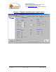
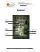
Table Of Contents

Dekolink WIRELESS Ltd.
16 Bazel St. Qiryat-Arieh Petah-Tikva, Israel, 49510
Tel- 972-3-9180-180 Fax-972-3- 190-9180
e-mail: marketing@dekolink.com
web www.dekolink.com
50W rev 1 10/03 Page 11 of 16
5.4. Installation steps
5.4.1. Install all antennas. Measure the isolation between the two antennas. The
isolation limits the maximum gain for the repeater. For a 90dB gain; an isolation
of over 102 dB is required. Lower isolation will increase noise. Isolation lower
than or equal to repeater gain would start oscillations within the repeater.
5.4.2. Measure the channel power reaching the base input of the repeater. This
sets the recommended repeater gain. For example; 4 signals are received at –
49dBm each (total power of –43dBm). Since the maximum composite power of
the repeater is +40dBm, the gain setting should be over 40+43 = 83dB in order
to get maximum power from the repeater. In this case isolation of over 95dB is
necessary for proper operation.
5.4.3. Connect the antenna cables to the repeater ports.
5.4.4. Turn on the downlink ALC (the ALC is always on at the uplink preamplifier).
This ALC limits the output power of the repeater. The ALC at the downlink path
guarantees constant downlink power when and if the donor power changes.
5.4.5. Set repeater gain to the calculated value (as in par. 2 above) using the SW
package. Turn on the RF power amplifier.
5.4.6. Set the uplink channel gain as required (usually the same gain as in the
downlink path is used).
5.4.7. Note the measured FWD Power indicating proper functionality of the
repeater.
WARNING
: Do not set the repeater RF gain higher than 12 dB below the measured antenna
isolation.
WARNING:
Check that the LED on the uplink power amplifier indicating uplink composite
power does not lit permanently. This LED would light permanently if the isolation between
antennas is low (indicating oscillation) or the repeater is faulty. During normal operation this
LED may flicker if a nearby mobile is in use.