
User Manual
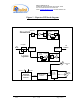
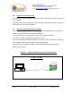
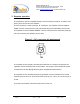
Table Of Contents

Dekolink WIRELESS Ltd.
16 Bazel St. Qiryat-Arieh Petah-Tikva, Israel, 49510
Tel- 972-3-9180-180 Fax-972-3- 190-9180
e-mail: marketing@dekolink.com
web www.dekolink.com
50W rev 1 10/03 Page 10 of 16
5. Repeater installation
Install the repeater in a shielded, ventilated and easy to reach area. Use low loss cables to
connect antennas to the repeater. Install the repeater close to the service area to improve
output power and noise figure.
The repeater’s “BASE” connector port is connected to donor antenna (usually a Yagi
antenna), while the repeater’s “MOBILE” connector port is connected to a mobile antenna or
Distributed Antenna System – DAS (outdoor or indoor).
5.1. Donor side antenna installation
Typically this is a directional antenna such as a Yagi or Dish antenna of 10 to 15dB gain. This
antenna points to the base station in order to get maximum input power. It should be installed
in “line of sight” with the base site. If no line of sight is achieved it is recommended to raise
the antenna higher until the line of sight is reached. The signals received from the base
station that are to be retransmitted should be the dominant (at least 6dB higher than other
received signals in the vicinity).
Attention to the minimal antenna isolation needed should be carefully considered. Choose the
antenna site to get the maximum isolation from the remote (mobile serving) antenna.
5.2. Service side antenna Installation
For outdoor applications the remote antenna is a directional antenna depending on the
coverage requirements.
For indoor applications covering a large building, the RF signals are usually split using power
dividers and distributed antenna systems, each covering a floor or a smaller area.
5.3. Antenna isolation
For proper operation the isolation between the donor side and service side antennas must be
at least 12dB higher than the repeater’s gain. Lower isolation leads to high in-band ripple and
noise. Oscillations appear when the isolation is lower than repeater set gain.
To measure the isolation; inject a known signal into one antenna and measure the power at
the other antenna. This should be done across the frequency range of both uplink and
downlink bands.