Dekolink WIRELESS Ltd. 16 Bazel St. Qiryat-Arieh Petah-Tikva, Israel, 49510 Tel- 972-3-9180-180 Fax-972-3-9180-190 e-mail: marketing@dekolink.com web www.dekolink.com INSTALLATION AND OPERATING INSTRUCTIONS FOR HIGH POWER PCS REPEATER MODEL: MW-BDA-PCS-F-50W90 Dekolink Wireless Proprietary and Confidential Information. Copying, Distribution, and Disclosure are prohibited without Express Authorization from Dekolink Wireless Company.
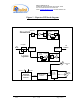
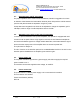
Dekolink WIRELESS Ltd. 16 Bazel St. Qiryat-Arieh Petah-Tikva, Israel, 49510 Tel- 972-3-9180-180 Fax-972-3-9180-190 e-mail: marketing@dekolink.com web www.dekolink.com Table of contents .1 Repeater overview ___________________________________________________________ 3 .2 Block diagram description _____________________________________________________ 3 .2.1 Step attenuator and RF gain setting ______________________________________________ 5 .2.
Dekolink WIRELESS Ltd. 16 Bazel St. Qiryat-Arieh Petah-Tikva, Israel, 49510 Tel- 972-3-9180-180 Fax-972-3-9180-190 e-mail: marketing@dekolink.com web www.dekolink.com 1. Repeater overview Dekolink’s repeater assembly provides an exceptional capability to extend the coverage area of radio communications into building areas and RF shielded environments. The unit’s integrated high linearity power amplifiers contribute to the overall improved system performance while avoiding non-linear related phenomena.
Dekolink WIRELESS Ltd. 16 Bazel St. Qiryat-Arieh Petah-Tikva, Israel, 49510 Tel- 972-3-9180-180 Fax-972-3-9180-190 e-mail: marketing@dekolink.com web www.dekolink.
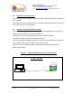
Dekolink WIRELESS Ltd. 16 Bazel St. Qiryat-Arieh Petah-Tikva, Israel, 49510 Tel- 972-3-9180-180 Fax-972-3-9180-190 e-mail: marketing@dekolink.com web www.dekolink.com 2.1. Step attenuator and RF gain setting For proper operation and in order to avoid oscillations, Dekolink’s suggestion is to have an isolation value between the base station antenna (donor side) and the mobile antenna (service side) that exceeds the repeaters’ set gain by 12dB.
Dekolink WIRELESS Ltd. 16 Bazel St. Qiryat-Arieh Petah-Tikva, Israel, 49510 Tel- 972-3-9180-180 Fax-972-3-9180-190 e-mail: marketing@dekolink.com web www.dekolink.com 2.5. Repeater connection module The connection module supplies and monitors the DC power to all the active components of the repeater. The repeater values are sampled here and, if needed, the relevant alarms are sent to the remote monitoring and control. Module 2.6.
Dekolink WIRELESS Ltd. 16 Bazel St. Qiryat-Arieh Petah-Tikva, Israel, 49510 Tel- 972-3-9180-180 Fax-972-3-9180-190 e-mail: marketing@dekolink.com web www.dekolink.com 3. Repeater operation The repeater AC power is supplied through a 3-wire male plug connector. A switch on the power control unit turns on the repeater. The RF connection is made via 2 type “N” connectors. The repeater connector labeled “BASE” must be connected to the roof antenna pointing to the base station (donor side).
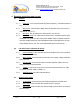
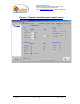
Dekolink WIRELESS Ltd. 16 Bazel St. Qiryat-Arieh Petah-Tikva, Israel, 49510 Tel- 972-3-9180-180 Fax-972-3-9180-190 e-mail: marketing@dekolink.com web www.dekolink.com 4. Repeater monitoring and control 4.1. Controls 4.1.1. PAmp On: Turns on/off the downlink power amplifier (√ indicates amplifier is on) 4.1.2. Max Power: This window is blank when the downlink ALC is turned off (√ indicates DL ALC is on) 4.1.3. Max Gain: The repeater gain is selected from a choice list 4.1.4.
Dekolink WIRELESS Ltd. 16 Bazel St. Qiryat-Arieh Petah-Tikva, Israel, 49510 Tel- 972-3-9180-180 Fax-972-3-9180-190 e-mail: marketing@dekolink.com web www.dekolink.
Dekolink WIRELESS Ltd. 16 Bazel St. Qiryat-Arieh Petah-Tikva, Israel, 49510 Tel- 972-3-9180-180 Fax-972-3-9180-190 e-mail: marketing@dekolink.com web www.dekolink.com 5. Repeater installation Install the repeater in a shielded, ventilated and easy to reach area. Use low loss cables to connect antennas to the repeater. Install the repeater close to the service area to improve output power and noise figure.
Dekolink WIRELESS Ltd. 16 Bazel St. Qiryat-Arieh Petah-Tikva, Israel, 49510 Tel- 972-3-9180-180 Fax-972-3-9180-190 e-mail: marketing@dekolink.com web www.dekolink.com 5.4. Installation steps 5.4.1. Install all antennas. Measure the isolation between the two antennas. The isolation limits the maximum gain for the repeater. For a 90dB gain; an isolation of over 102 dB is required. Lower isolation will increase noise.
Dekolink WIRELESS Ltd. 16 Bazel St. Qiryat-Arieh Petah-Tikva, Israel, 49510 Tel- 972-3-9180-180 Fax-972-3-9180-190 e-mail: marketing@dekolink.com web www.dekolink.com 6. Specifications 6.1.
Dekolink WIRELESS Ltd. 16 Bazel St. Qiryat-Arieh Petah-Tikva, Israel, 49510 Tel- 972-3-9180-180 Fax-972-3-9180-190 e-mail: marketing@dekolink.com web www.dekolink.
Dekolink WIRELESS Ltd. 16 Bazel St. Qiryat-Arieh Petah-Tikva, Israel, 49510 Tel- 972-3-9180-180 Fax-972-3-9180-190 e-mail: marketing@dekolink.com web www.dekolink.
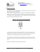
Dekolink WIRELESS Ltd. 16 Bazel St. Qiryat-Arieh Petah-Tikva, Israel, 49510 Tel- 972-3-9180-180 Fax-972-3-9180-190 e-mail: marketing@dekolink.com web www.dekolink.com 7. RF exposure warning In order to satisfy the FCC RF exposure requirements, you must ensure that the installation complies with the following: One antenna is connected via cable that has typical 1~10 dB attenuation (depends on the length of the cable) to the BDA base port.
Dekolink WIRELESS Ltd. 16 Bazel St. Qiryat-Arieh Petah-Tikva, Israel, 49510 Tel- 972-3-9180-180 Fax-972-3-9180-190 e-mail: marketing@dekolink.com web www.dekolink.com 8. Limited warranty Dekolink Wireless [Ltd.