
User's Manual


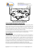


Table Of Contents

Dekolink WIRELESS Ltd.
16 Bazel St. Qiryat-Arieh Petah-Tikva, Israel, 49510
Tel- 972-3-9180-180 Fax-972-3- 190-9180
e-mail: marketing@decolink com web www decolink com
Page
6 of 14 50W rev 4 02/04
BDA MONITOR FUNCTIONS
P.S. (Uplink & down link) Illuminates when the Power Supply voltage is below or above
its limits.
P.AMP. (Uplink) Illuminates when the uplink Power Amplifier current is above or below
its specified limits
P.AMP. (Downlink) Illuminates when the uplink RF Power is 10 dB below the specified
composite power.
L.N.A. (Uplink & Downlink) Illuminates when the Low Noise Amplifier current is above
or below its specified limits.
AGC Range. (Downlink) This green LED on the downlink path illuminates when the
transmitted power reaches or exceeds the AGC set power, which is the maximum
specified composite power. For best efficient use of repeater RF power this LED should
be on.
AGC Range. (Uplink) This green LED on the downlink path illuminates when the
transmitted power reaches or exceeds the AGC set power, which is the maximum
specified composite power. This LED should not lit permanently. It lights only when a
nearby mobile is transmitting.
The Pushbutton Switch on the BDA monitor turns on all the alarms. This is used to
test the alarm functions of the BDA.
REMOTE ALARM
The BDA monitor has a dry contact relay arms output. These
contacts are short circuit at no fault and open circuit at any fault or at power loss. This
function can be used to operate a modem for remote alarm warning. The relay contacts
are connected to pins A and C (small pins) on the alarm connector at the front panel.