
User Manual
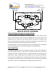
Table Of Contents

Dekolink WIRELESS Ltd.
16 Bazel St. Qiryat-Arieh Petah-Tikva, Israel, 49510
Tel- 972-3-9180-180 Fax-972-3- 190-9180
e-mail: marketing@dekolink com web www dekolink com
Page 9 of 14 50W rev 3 08/03
INSTALLATION STEPS
1. Install all antennas and connect them to the BDA inputs.
2. Turn the AGC On. This AGC limits the output power of the BDA. The AGC on the
Downlink path guarantees constant downlink power when and if the Donor power
changes.
3. Set downlink gain to minimum; uplink gain to minimum.
4. Increase the downlink channel gain till the green LED turns from off to on. This is
the best gain setting giving highest usable power.
5. The green LED on the downlink power amplifier will illuminate if adequate donor
power has reached the BDA. If the donor power is low the LED will not lit and the
BDA usable power is not used efficiently. The red LED will illuminate if the donor
power is 10 dB or more below the maximum usable power indicating a fault.
6. Set the uplink gain to the same as the downlink gain.
7. Check that the uplink green LED on the BDA monitor does not lit permanently. This
LED would lit permanently If the isolation between antennas is low (BDA
oscillations) or the BDA is faulty. In such a case:
• Disconnect one of the cables from the BDA connectors and connect a load
at the connectors.
• If the LED on this amplifier illuminates permanently then the BDA is faulty
(oscillating) and needs replacing.
• If the LEDs stops illuminating then the isolation between the donor and
remote antennas is low. Either improve the isolation (e.g. increase
separation) or reduce BDA gain.
• To reduce gain, reconnect the antenna cables. Reduce the gain at both
uplink and downlink path until this LED stops illuminating. Reduce the gain
further by 10 dB. This is the maximum usable gain.