
User Manual
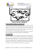
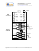
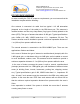
Table Of Contents

Duplexer
Downlink
Duplexer
Uplink
LNA
Attenuator
Power
Monitor
PA
AGC
LNA
Attenuator
Power
Monitor
PA
AGC
BDA RF BLOCK DIAGRAM
TO
BASE
TO
MOBILE
Page 4 of 14 50W rev 3 08/03
Dekolink WIRELESS Ltd.
16 Bazel St. Qiryat-Arieh Petah-Tikva, Israel, 49510
Tel- 972-3-9180-180 Fax-972-3- 190-9180
e-mail: marketing@dekolink com web www dekolink com
STEP ATTENUATOR AND RF GAIN SETTING
For proper operation of the Repeater, the isolation between the base station antenna
and the mobile antenna should exceed the Repeater gain by at least 12 dB. If the
Repeater gain were higher than the isolation between the antennas, oscillation would
start and would saturate the amplifier. Isolation few dB higher than the Repeater gain
cannot start oscillations but would cause gain ripple in the band.
The step attenuator on the low noise amplifier reduces the Repeater gain. The Repeater
gain can be stepped down by the amount indicated on the step attenuator.
AGC FUNCTION
The Repeater has AGC function on both paths that serve to prevent the saturation of
the power amplifier. When a high signal is received the AGC circuit detects the
amplitude and sends a feedback signal to a variable attenuator, which attenuates the
signal level so that the output power of the amplifier does not exceed the preset limit.
The green LED on the BDA monitor (AGC Range) illuminates when the power output of
the amplifier is within the set limit. An On/Off switch on the connection box enables the
AGC function. If the AGC is disabled then the amplifier gives maximum gain.