
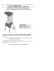
Specifications


•
ATTACHING MULCH
BAG
Place
a
heavy duty garbage
bag
over
the lip of the
discharge
chute
and
secure into position using
a
strap.
Fig.
8
•
MAINTENANCE
Your
ECO-SHREDDER
has
been designed
for a low
level
of
maintenance,
involving
routine cleaning
and
inspection.
The
motor
of the
machine
is
maintenance free
and
requires
no
attention.
For
best results
the
blades must
be
kept sharp
at
all
times.
The
blades have dramatically less cutting power
when
dull.
The
machine will tear rather than
cut
when
the
blades
are
dull. When this occurs rotate
the
double sided
blades
or
replace
the
blades immediately.
WARNING
Before
attempting
any
maintenance, switch
the
machine
off
and
disconnect
the
power cord from
power
source.
•
JAMMING
If
blades become jammed, switch
off the
machine
and
disconnect
the
power cord from
the
power source. Always
wear
gloves when attempting maintenance
of the
cutting
chamber. Unscrew
the 3
securing
Top
Hopper
assembly
knobs. Remove
the Top
Hopper assembly
and
remove
the
obstruction from
the
cutting chamber.
WARNING
Take
extreme care
not to
come
in
contact with
cutting blades. Assemble
the Top
Hopper
in
reverse
order
stated
above.
WARNING
If
ejection chute becomes
clogged
or
cutting blades
become jammed, under
no
circumstances should
you
place
your hands
in the
ejection
chute
to try to
clear
the
obstructbn
as
this will lead
to
serious
injury.
.
V-CUTTER
MAINTENANCE
•
Switch
the
machine
off and
disconnect
the
power cord
ensuring
all
moving parts
are
comptetely
stopped.
•
Wear gloves when attempting
any
maintenance
to the
cutting
blades.
• If
blades require replacing, ensure
you use
DUROSTAR
genuine
parts.
>
DISASSEMBLY
I.
Unscrew
the 3 Top
Hopper assembly knobs
and
remove
the Top
Hopper assembly.
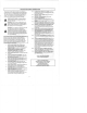
!.
Rotate
the
cutter base counter clockwise
and
place
a
piece
of
wood between
the
cutter base
and the
cutting
chamber
wall
so as to
stop
the
cutting base from
rotating.
Fig.
9
i.
Remove
the
center hold down bolt
by
turning
it
counter
clockwise using
a
wrench.
t.
Remove
the
square washer, square bushing,
V-cutter
and
V-cutter base
to
expose
the
cutter base.
•
SHREDDING BLADES MAINTENANCE
To
inspector
replace
the
double sided shredding blades
there
is no
need
to
remove
the
V-cutter
or
cutting
base.
To
remove
simply undo
the
countersunk screws with
the hex
wrench provided
wrth
the
machine
and
turn them 180°.
These blades
are
double
ground
and can be
used
on
both
skies.
When
dull
on
both sides replace with
new
blades
and
make
sure
they
are
screwed
in
tightly.
•
ASSEMBLY
This
is
carried
out in the
reverse order
to
that
of the
disassembly
but
with careful inspection
of all
components.
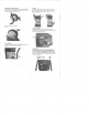
Ensure
that
the
cutter base
is
assembled with
the
scraping
plates facing down
towards the
motor
and
that
the
spring
washer
is
situated under
the
head
of the
center hold down
bolt.
Fig.
10
Before
replacing
the top
cover assembly, ensure that
the
V-cutter
is
positioned
as
shown
in
Fig.
11.
Replace
the Top
Hopper assembly
and
secure with
the
three
(3)
Top
Hopper
assembly
knobs.
Fig.
10
•
CLEANING
After
use, always
wipe
clean
the
outside
of the
machine
to
remove
any
build
up of
material with
a
damp cloth.
Clean
the
inside
of the
cutting chamber
and
remove
any
left
over material.
-3-