
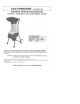
Specifications


•
ASSEMBLE FRAME
&
WHEELS
Align
the
holes
in the
wheels
to the
holes
in the
axle
section
of
the
frame
and
secure tightly with
the
bolts,
spring washers
and
nuts provided
as
shown
in
Fig.
1.
Affix
the hub
caps
to the
wheels.
Fig.
2
.
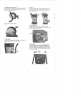
TOP
HOPPER
Place
the Top
Hopper onto
the
metal feed tube
and
align
the
attaching
holes.
Secure
the one way
screw.
•
HANDLE
Insert
the
handle
bar
into
the
handle shafts located
at
the
rear
of the
machine. Align
the
holes
in the
handle
bar
to the
holes
in the
handle shafts
and
secure with
the 2
knobs
as
shown
in
Fig.
4 & 5.
.
SAFTEY SWITCH
The
safety switch that
is
located
on the
cutter base
is
activated
when
the Top
Hopper assembly
is
removed
to
help
prevent accidental starting. Fig.
6
.
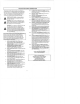
OPERATION
Read
and
understand
the
safety instructions
in
this
owner's manual before using your ECO-SHREDDER.
Connect
the
machine
to a
suitable power outlet.
To
start
the
machine, place
the
On/Off switch located
at the
rear
of the
motor
to
"ON" position. Fig.
7. To
stop
the
machine, switch
to
the
"OFF"
position.
-2-