
Installation guide

www.clifford.com
9
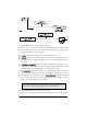
H1/11 RED (+)12V constant power input
Before connecting this wire, remove the supplied fuse. Connect to the battery positive terminal or
the constant 12V supply to the ignition switch.
NOTE: Always use a fuse within 12 inches of the point you obtain (+)12V. Do not use the 15 fuse
in the harness for this purpose. This fuse protects the module itself.
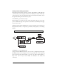
H1/12 RED/WHITE output of channel 2 relay #30
Whenever the button(s) controlling channel two is pressed for 1.5 seconds, the on-board relay is
activated and will stay activated as long as the transmission continues. This relay is often used for
trunk release. The relay can drive circuits up to 20 amperes. The polarity of this output is deter-
mined by the connection of the input wire H2/A in the Relay Harness.
NOTE: If the input wire H2/A is not connected, there will be no output from the relay when it is
activated.
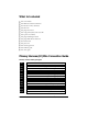
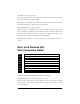
Door Lock Harness (H2)
Wire Connection Guide
___
___
___
___
___
___
___
___
*NOTE: VIOLET AND VIOLET/BLACK are common at fuse holder.
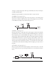
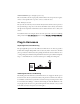
H2/A RED/WHITE input to on-board channel 2 (trunk release) relay
This wire is used to supply voltage to the output H1/12. If you want a positive output on H1/12,
connect this wire to +12V. Always fuse appropriately. If a negative output is desired, connect this
wire to chassis ground.
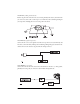
VIOLET* Unlock #87 Normally Open (Input)
BLUE/BLACK Unlock #30 Common (Output)
BROWN/BLACK Unlock #87A Normally Closed
VIOLET/BLACK* Lock #87 Normally Open (Input)
GREEN/BLACK Lock #30 Common (Output)
WHITE/BLACK Lock #87A Normally Closed
BLACK/WHITE Domelight Supervision Relay Input #87
RED/WHITE Channel 2 Relay Input #87
H2/A
H2/B
H2/C
H2/D
H2/E
H2/F
H2/G
H2/H