
Installation guide

4
©
2001
Directed Electronics, Inc.
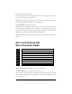
What Is Included
➤➤
One control module
➤➤
One XHF receiver/antenna with harness
➤➤
Two four-button remote transmitters
➤➤
One 514C siren
➤➤
One plug-in shock sensor
➤➤
One 12-pin primary harness with starter kill
➤➤
One 8-pin door lock harness
➤➤
One plug-in Valet/Program switch
➤➤
One plug-in LED indicator with bezel
➤➤
Two window decals
➤➤
One patent card
➤➤
One warranty registration
➤➤
One installation guide
➤➤
One owner’s guide
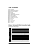
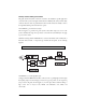
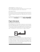
Primary Harness (H1) Wire Connection Guide
Primary Harness Wiring Diagram
___
___
___
___
___
___
___
___
___
___
___
___
RED/WHITE Output of Channel 2 Relay #30
RED (+) Constant Power Input
BROWN (+) Siren Output
YELLOW (+) Switched Ignition Input, Zone 5
BLACK (-) Chassis Ground Input
VIOLET (+) Door Trigger Input, Zone 3
BLUE (-) Instant Trigger Input, Zone 1
GREEN (-) Door Trigger Input, Zone 3
BLACK/WHITE Output of Domelight Supervision Relay #30
WHITE/BLUE (-) 200 mA Channel 3 Programmable Output
WHITE (+)/(-) Selectable Light Flash Output
ORANGE (-) 500 mA Ground-When-Armed Output
H1/1
H1/2
H1/3
H1/4
H1/5
H1/6
H1/7
H1/8
H1/9
H1/10
H1/11
H1/12