Matrix 3 Installation Guide © 2001 Directed Electronics, Inc. N909449 8-01 Rev. N/C 1.
The Bitwriter® (p/n 998T) requires chip version 1.4 or newer to program this unit. Bitwriter™, Code Hopping™, DEI®, Directed®, Doubleguard®, ESP™, FailSafe®, Ghost Switch™, Learn Routine™, Nite-Lite®, Nuisance Prevention Circuitry®, NPC®, Revenger®, Silent Mode™, Soft Chirp®, Stinger®, Valet®, Vehicle Recovery System®, VRS®, and Warn Away® are all Trademarks or Registered Trademarks of Directed Electronics, Inc., Vista, California.
Table of Contents What is Included ...........................................4 Primary Harness (H1) Wire Connection Guide ................................4 Primary Harness Wiring Diagram..............4 Primary Harness Wiring Instructions.........5 Door Lock Harness (H2) Wire Connection Guide ................................9 Plug-IIn Harnesses ........................................10 Super Bright LED....................................10 Valet/Program Switch ..............................
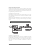
What Is Included ➤ ➤ ➤ ➤ ➤ ➤ ➤ ➤ ➤ ➤ ➤ ➤ ➤ ➤ One control module One XHF receiver/antenna with harness Two four-button remote transmitters One 514C siren One plug-in shock sensor One 12-pin primary harness with starter kill One 8-pin door lock harness One plug-in Valet/Program switch One plug-in LED indicator with bezel Two window decals One patent card One warranty registration One installation guide One owner’s guide Primary Harness (H1) Wire Connection Guide Primary Harness Wiring Diagram 4 H1/1 ___
Primary Harness Wiring Instructions This guide describes in detail the connection of each wire. Also included are possible applications of each wire. This system was designed with the ultimate in flexibility and security in mind. Many of the wires have more than one possible function. Please read the instructions carefully to ensure a thorough understanding of this unit and how it operates. H1/1 ORANGE (-) ground-when-armed output This wire supplies a (-) ground as long as the system is armed.
H1/3 WHITE/BLUE 200 mA (-) channel 3 programmable output This wire provides a (-) 200 mA output whenever the transmitter button(s) controlling channel three is pressed. This output can be programmed to provide the following types of output (see System Features Learn Routine section of this guide): ➤ ➤ ➤ ➤ ➤ A validity output will send a signal as long as the transmission is received. A latched output will send a continuous signal after the button controlling channel three is pressed and released.
circuits up to 20 amperes. The polarity of this output is determined by the connection of the input wire H2/B in the Relay Harness. NOTE: If the input wire H2/B is not connected, there will be no output on this wire. H1/5 GREEN (-) door trigger input, zone 3 Most vehicles use negative door trigger circuits. Connect the green wire to a wire showing ground when any door is opened. In vehicles with factory delays on the domelight circuit, there is usually a wire unaffected by the delay circuitry.
H1/8 BLACK (-) chassis ground connection Remove any paint and connect this wire to bare metal, preferably with a factory bolt rather than your own screw. (Screws tend to either strip or loosen with time.) We recommend grounding all your components, including the siren, to the same point in the vehicle. H1/9 YELLOW (+) ignition input, zone 5 Connect this wire to the (+)12V ignition wire. This wire is pre-wired to the starter kill relay and must show (+)12V with the key in Run position and during cranking.
H1/11 RED (+)12V constant power input Before connecting this wire, remove the supplied fuse. Connect to the battery positive terminal or the constant 12V supply to the ignition switch. NOTE: Always use a fuse within 12 inches of the point you obtain (+)12V. Do not use the 15 fuse in the harness for this purpose. This fuse protects the module itself. H1/12 RED/WHITE output of channel 2 relay #30 Whenever the button(s) controlling channel two is pressed for 1.
H2/B BLACK/WHITE input to domelight supervision relay This wire determines what the output polarity of H1/4 will be. If the door pin circuit is negative, connect to chassis ground. If the it is positive, connect to a fused 12V source. H2/C - H2/H power door locks The system has door lock relays on-board, and can directly interface with most electric power door lock systems drawing 30 amps or less. It can also drive aftermarket actuators directly.
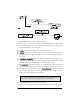
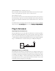
Programmer Interface, 3-Pin Black Plug The black 3-pin port is provided for personal computer programming of the unit. When using the Directed Bitwriter (P/N 998T) or optional PC Interface Module (P/N 996T) it is possible to configure any and all of the programmable functions. The PC Interface Module works with an IBM compatible PC. (The 998T does not require the IBM compatible PC.) For more information please refer to the guide packaged with the programmer.
Programming Jumper Light Flash Jumper This jumper is used to determine the light flash output. In the (+) position, the on-board relay is enabled and the unit will output (+)12V on the WHITE wire, H1/2. In the (-) position, the onboard relay is disabled. The WHITE wire, H1/2, will supply a 200 mA (-) output suitable for driving factory parking light relays. NOTE: For parking light circuits that draw 10 amps or more, the jumper must be switched to a (-) light flash output.
System Features Learn Routine The System Features Learn Routine dictates how the unit operates. Due to the number of steps, they have been broken up into two menus. It is possible to access and change any of the feature settings using the Valet/Program switch. However, this process can be greatly simplified by using the optional Directed Bitwriter or Personal Computer Interface, P/N 996T.
you wish to access, release the button and go on to Step 4. If the button is not released, you will jump to the Advanced Features Menu #2 and the siren will chirp twice. Once you have selected the desired menu, release the Valet/Program button and then proceed to Step 4. 4. Select a Feature. Press and release the Valet/Program switch the number of times corresponding to the feature you wish to change. For example, to access the third feature, press and release the switch three times.
To select another menu: 1. Press and HOLD the Valet/Program switch. 2. After three seconds, the unit will advance to the next menu and the siren will chirp, indicating which menu has been accessed. For instance, if you just programmed some features in Menu #1 (Basic Features) and you wish to program a feature in Menu #2, you press and HOLD the Valet/Program button. After three seconds, the siren chirps twice indicating access to Menu #2.
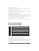
Menu #2 - Advanced Features Feature Number One Chirp Setting (Default) Two-Chirp Setting 2-1 Siren Horn honk 2-2 30-second siren duration 60-second siren duration 2-3 False Alarm Control Technology ON False Alarm Control Technology OFF 2-4 Progressive door trigger Instant door trigger 2-5 Valet switch input: 1 pulse Valet switch input: 2-5 pulses 2-6 Door trigger error chirp ON Door trigger error chirp OFF 2-7 Ignition-controlled domelight ON Ignition-controlled domelight OFF 2-8 Si
system is armed via the transmitter. Active locking means the system will not lock the doors when it passively arms. Passive locking means that the system will lock the doors when it passively arms. NOTE: Remember, when passive arming is selected, the unit will chirp 20 seconds after the last door is closed. The system does not actually arm or lock the doors until 30 seconds after the door has been closed.
Menu #2 - Advanced Features 2-1 SIREN/HORN HONK: The system can be programmed to output pulses instead of a continuous output when the system is triggered. This is useful to honk the factory horn in applications where a siren is undesirable. Remember that the unit is only capable of supplying 1 amp of current. A relay will be required to interface with most factory horn systems. 2-2 SIREN DURATION 30/60 SECONDS: It is possible to program the unit to sound for 30 or 60 seconds during the triggered sequence.
2-6 DOOR TRIGGER ERROR CHIRP ON/OFF: With the door trigger error chirp programmed off, the system will not report an invalid zone on arming when the door trigger wire is active. This eliminates the extra chirps that occur when interfacing with vehicles that have exceptionally long dome light delay circuits. 2-7 IGNITION-CONTROLLED DOMELIGHT SUPERVISION ON/OFF: If turned on, the system will turn on the domelight for 30 seconds when the ignition is turned off.
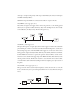
2. Key. Turn the ignition on. (The YELLOW wire, H1/9 must be connected.) 3. Select the receiver channel: Press and release the Valet/Program switch the number of times necessary to access the desired channel. Press and HOLD the Valet/Program switch once more. The siren will chirp and the LED will blink the number of times corresponding to the channel that has been accessed.
on the remote control. These channels are only available when using an optional Radar Master remote. (See Transmitter Configurations section of this guide.) Teaching a transmitter button to Channel 4 erases all previous programming from the transmitter’s memory.
Transmitter Configurations Using the Auto Learn functions in the Transmitter/Receiver Learn Routine, the transmitters can be programmed either with the 3-button configuration or 4-button configuration. 3-Button Transmitter Configuration This configuration can be programmed to an optional 3-button transmitter using Channel 7 of the Transmitter/Receiver Learn Routine. The transmitter buttons are assigned to the following functions: ..........................operates ......................Arm/Disarm/Panic ...
Multi-Level Security Arming Multi-Level Security Arming is only available when using an optional Radar Master transmitter that has been configured with separate transmitter buttons for arming and disarming. Multi-Level Security Arming allows you to select which of the system's inputs or sensors will be active or bypassed at the time that the system is armed. (See Table of Zones section.) Pressing the arm button again within five seconds of arming the system will activate Multi-Level Security Arming.
Table of Zones When using the diagnostic functions, use the Table of Zones to see which input has triggered the system. It is also helpful in deciding which input to use when connecting optional sensors and switches. NOTE: The Warning Zone response does not report on the LED. Zone No. Trigger type Input description 1 Instant H1/6 BLUE wire. Connect to optional hood/trunk pins. 2 Multiplexed Input ORANGE wire of plug-in shock sensor. Inputs shorter than 0.
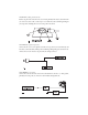
4. Press and release the Valet/Program switch within 5 seconds. The LED will flash in groups indicating the last two zones that triggered the unit. The LED will flash for one minute or until the ignition is turned off. NOTE: The Warning Zone triggers are not stored to memory and will not be reported. Optional Vehicle Recovery System (VRS) No additional parts are required to add the optional VRS feature. However for the VRS feature to be effective, the 8618 Starter Kill Relay must be installed.
To disarm VRS (after the siren has begun chirping): 1. Turn the ignition to the ON position. 2. Press and release the Valet/Program switch the selected number of times programmed in Step 2-5. (See System Features Learn Routine section of this guide.) NOTE: For a detailed explanation to the VRS triggered sequence, refer to the Vehicle Recovery System section of the Owner's Guide.
Shock sensor does not trigger the alarm. ➤ Has the FACT system been triggered? If so, you will hear five chirps when disarming. To check this, turn the ignition key on and off to clear the FACT from memory, and then retest the shock sensor. Door input does not immediately trigger full alarm. Instead, I hear chirps for the first three seconds. ➤ That’s how the progressive two-stage door input works! This is the instant response feature of this system.
Wiring Quick Reference Guide 28 © 2001 Directed Electronics, Inc.