Matrix RS2 Installation Guide © 2001 Directed Electronics, Inc. N909553 7-01 Rev. N/C 1.
The Bitwriter® (p/n 998T) requires chip version 1.4 or newer to program this unit. Bitwriter™, Code Hopping™, DEI®, Directed®, Doubleguard®, ESP™, FailSafe®, Ghost Switch™, Learn Routine™, Nite-Lite®, Nuisance Prevention Circuitry®, NPC®, Revenger®, Silent Mode™, Soft Chirp®, Stinger®, Valet®, Vehicle Recovery System®, VRS®, and Warn Away® are all Trademarks or Registered Trademarks of Directed Electronics, Inc., Vista, California.
Table of Contents What Is Included ...........................................4 Warning! Safety First .....................................4 Installation Points to Remember ....................5 Before Beginning the Installation...............5 Finding the Tachometer Wire ....................6 Finding the Wait-to-Start Bulb Wire for Diesels..................................................6 After the Installation..................................7 Primary Harness (H1) Wire Connection Guide .................
What Is Included The following components are included with this installation kit: ➤ ➤ ➤ ➤ ➤ ➤ ➤ ➤ ➤ ➤ One control module One XHF receiver/antenna Two four-button remote transmitters One 514C siren One plug-in LED indicator with bezel The plug-in Valet/program switch One plug-in shock sensor A hood pinswitch A toggle override switch One 5-pin harness with relay satellite ➤ ➤ ➤ ➤ ➤ ➤ ➤ ➤ ➤ ➤ 12-Pin, 11-wire primary harness (H1) 3-Pin auxiliary harness (H2) 3-Pin door lock harness (H4) 6-Pin remote start h
➤ ➤ Use of this product in a manner contrary to its intended mode of operation may result in property damage, personal injury, or death. Except when performing the Safety Check outlined in this installation guide, (1) Never remotely start the vehicle with the vehicle in gear, and (2) Never remotely start the vehicle with the keys in the ignition.
➤ ➤ ➤ air bag, avoid disconnecting the battery if possible. Many airbag systems will display a diagnostic code through their warning lights after they lose power. Disconnecting the battery requires this code to be erased, which can require a trip to the dealer. Check with the customer on LED status indicator location. Remove the domelight fuse. This prevents accidentally draining the battery. Roll down a window to avoid being locked out of the car.
5. If the meter indicates 12 volts until the light goes out you have isolated the correct wire and the wire's polarity is negative (ground while the bulb is on). 6. If the meter reads zero volts until the light goes out and then reads 12 volts, you have isolated the correct wire and the wire's polarity is positive. After the Installation ➤ ➤ ➤ Test all functions. The “Using Your System” section of the Owner's Guide is helpful for testing.
H1/1 ORANGE (-) Ground-When-Armed Output This wire supplies a (-) 500 mA ground as long as the system is armed. This output ceases as soon as the system is disarmed. The ORANGE wire is pre-wired to control the Directed P/N 8618 starter interrupt relay. NOTE: If connecting the H1/1 ORANGE wire to control another module, such as a P/N 529T or P/N 530T window controller, a 1 amp diode (type 1N4004) is required.
(+) POSITIVE LIGHT FLASH OUTPUT (-) LIGHT FLASH OUTPUT H1/3 WHITE/BLUE Remote Start (-) Activation Input A momentary input on this wire will start or stop the motor, just as transmitting Channel 3 from the remote transmitter does. It is often connected to an optional momentary push-button switch to make access to Valet Take Over Mode and Timer Mode more convenient.
H1/5 GREEN (-) Door Trigger Input, Zone 3 Most vehicles use negative door trigger circuits. Connect the green wire to a wire which shows ground when any door is opened. In vehicles with factory delays on the domelight circuit, there is usually a wire that is unaffected by the delay circuitry. This wire will report Zone 3. H1/6 BLUE (-) Multiplex Input, Zone 4 Inputs shorter than 0.8 seconds will trigger the Warning Zone response, while inputs longer than 0.8 seconds will trigger the full alarm sequence.
H1/8 BLACK (-) Chassis Ground Connection Remove any paint and connect this wire to bare metal, preferably with a factory bolt rather than your own screw. (Screws tend to either strip or loosen with time.) We recommend grounding all your components, including the siren, to the same point in the vehicle. H1/10 BROWN (+) Siren Output Connect this to the red wire of the siren.
IMPORTANT! Never use this wire to drive anything except a relay or low-current input! The transistorized output can only supply 200 mA of current. Connecting directly to a solenoid, motor, or other high-current device will cause it to fail.
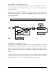
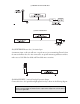
H2/2 LIGHT GREEN/BLACK (-) Factory Disarm Output This wire sends a negative pulse every time the remote engine starting system is activated. This can be used to pulse the disarm wire of the vehicle's factory anti-theft device. Use a relay to send a (-) or (+) pulse to the disarm wire as shown in the diagrams below. This wire can also be used as a special accessory output. (See Feature Descriptions section of this guide.) RELAY FOR NEGATIVE (-) DISARM WIRE www.clifford.
H2/3 VIOLET/BLACK (-) 200 mA Channel This wire provides a (-) 200mA output whenever the transmitter button(s) controlling Channel 4 is pressed. This output can be programmed to provide the following types of outputs (see also the Feature Menus section): ➤ ➤ ➤ ➤ ➤ Validity: Output that will send a signal as long as the transmission is received. Latched: Output that will send a signal when the Channel 4 button(s) is pressed and will continue until the same button(s) is pressed again.
Relay Satellite Key Switch Interface Wire Connection Guide (Heavy Gauge Wires) The five heavy gauge wires coming from the relay satellite are used to energize high current circuits in the vehicle. It is crucial that these connections are well-made and capable of handling the current demands. For this reason, Scotch-Locks, T-taps and other such connectors are strongly discouraged.
Remote Start Ribbon Plug-In Harness 1 ___ RED 2 ___ YELLOW (+) Ignition Input to Remote Start 3 ___ PINK (-) 200 mA Ignition Relay Turn-On 4 ___ ORANGE 5 ___ PURPLE (+) Constant Power (-) 200 mA Accessory Relay Turn-On (-) 200 mA Starter Relay Turn-On Remote Start Harness (H3) Wire Connection Guide H3/1 ___ BLUE H3/2 ___ BLUE/BLACK H3/3 ___ GRAY (-) Hood Pinswitch Input, Zone 1 H3/4 ___ BROWN (+) Brake Switch Shutdown Wire H3/5 ___ VIOLET/WHITE Tachometer Input Wire H3/6 ___ BLAC
H3/2 BLUE/BLACK (-) Optional Third Ignition Output This output provides a 200mA output as soon as the remote engine starting system is activated. It can be used to power a relay to energize a positive (+) third ignition as shown below. This output is capable of driving two relays if necessary. H3/3 GRAY (-) Hood Pinswitch Input, Zone 1 This wire MUST be connected to hood pinswitch. This input will disable or shut down the remote engine starting system when the hood is opened.
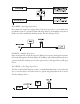
connected, you must teach the system the tach signal. (See the Programming Jumpers section of this guide.) H3/6 BLACK/WHITE neutral safety switch input Connect this wire to the provided toggle (override) switch as shown in figure A. Connect the other wire from the toggle switch to the park/neutral switch in the vehicle. This wire will test with ground with the gear selector either in PARK or NEUTRAL. This will prevent the vehicle from accidentally being started while in a drive gear.
Neutral Safety Switch Interface Some vehicles combine the column shift mechanism and the mechanical neutral safety switch into one mechanical part. In these vehicles, it is impossible to interface the remote engine starting system before the neutral safety switch. With this type of vehicle, if the vehicle is left in a drive gear and the remote engine starting system is activated, the vehicle will move and may cause damage to persons or property.
If the starter engages and the vehicle is a General Motors product or Dodge Dakota pickup, refer to the following text and diagrams for an alternative shut-down method which will prevent the starter from engaging. If the vehicle is not a General Motors product or a Dodge Dakota pickup, please call Directed Technical Support for an alternative shut-down method.
DIAGRAM A - GM TRUCKS, SPORT UTILITY VEHICLES AND COLUMN SHIFTING PASSENGER VEHICLES: DIAGRAM B - PRE-1996 DODGE DAKOTA PICKUPS WITH 2.5 LITER MOTORS: 1995 and Newer Vehicle Anti-Theft Systems (Immobilizers) 1995 and newer vehicle anti-theft systems (immobilizers) require a bypass module. The bypass module allows for easy interfacing, while still maintaining the OEM system’s integrity.
➤ ➤ ➤ ➤ ➤ ➤ 1995 and newer Cavalier and Sunfire 1996 and newer Achieva, Grand Am, and Skylark 1997 and newer Intrigue, Malibu, and Cutlass 1998 and newer trucks, vans, SUVs 1999 and newer Alero 2000 and newer Impala and Saturn Passlock I and II systems are VATS-evolved. Passlock systems still rely on the R-code to start, but the pellet is no longer placed in the key. The resistor can now be found in the key switch. This allows for a greater number of possible R-codes.
Bypassing GM Vehicle Anti-Theft Systems (VATS) Vehicles with the GM VATS (Pass Key) systems have a resistor embedded in the ignition key. If the VATS decoder module does not measure the proper resistance value when the vehicle is started, the starter and fuel pump may be disabled for up to ten minutes. An optional "VATS pack" of resistors is available (Directed P/N 652T). One of the resistors in the pack will match the resistor in the key.
Plug-In Harnesses Super Bright LED, 2-Pin White Plug The super bright LED operates at 2V DC. Make sure the LED wires are not shorted to ground as the LED will be damaged. Multiple LEDs can be used, but they must be wired in series. The LED can be top-mounted or flush-mounted. If top-loading the LED with a bezel, the LED fits into a 5 /16-inch mounting hole. If flush-mounting the LED from the back of a panel, drill a mounting hole using a 17/64-inch drill bit.
Shock Sensor Harness, 4-Pin Connector RED, BLACK These wires supply constant 12 volts and ground to the shock sensor. Do not use these wires for anything except the plug-in shock sensor. ORANGE (-) Multiplex Input, Zone 2 Inputs shorter than 0.8 seconds will trigger the Warning Zone response, while inputs longer than 0.8 seconds will trigger full alarm sequence and report zone four. If installing an additional Directed dual stage sensor, connect to the green wire as shown below.
Door Lock Harness (H4) Wire Connection Guide H4/A ___ GREEN (-) Lock, (+) Unlock Output H4/B ___ EMPTY Unless Using 451M H4/C ___ BLUE (-) Unlock, (+) Lock Output For detailed instructions on wiring the vehicle’s door locks, please refer to the Door Lock Wiring Document No. 1041) provided on the www. directechs.com website or through DirectFax Guide (D 1-8800-9999-11FAX (1329). Programming Jumpers Digital Tach Filter On/Off In most cases, this jumper can be left in the OFF position.
Light Flash Jumper This jumper is used to determine the light flash output. In the (+) position, the on-board relay is enabled and the unit will output (+)12V on the WHITE wire, H1/2. In the (-) position, the onboard relay is disabled. The WHITE wire, H1/2, will supply a 200 mA (-) output suitable for driving factory parking light relays. NOTE: For parking light circuits that draw 10 amps or more, the jumper must be switched to a (-) light flash output.
Channel Number Function Wire Color 1 Arm/disarm/panic 2 Chirp muting/remote controlled Valet/trunk release 3 Remote start 4 Auxiliary output 5 Arm only (only available with Radar Master remote)1 6 Disarm only (only available with Radar Master remote)1 7 Panic only (only available with Radar Master remote)1 8 Auto-learn 4-button transmitter configuration2 9 Zap (delete all transmitters)3 RED/WHITE VIOLET/BLACK NOTE: Channels 5, 6, and 7 are only available when using an optional Radar Ma
section of this guide). This is useful in cases where the one of the customer's transmitters is lost or stolen. This will erase any lost or stolen transmitters from the system's memory. It can also be used to start from scratch if the transmitter buttons were programmed incorrectly. To advance from one channel to another: You can advance from one channel to another by releasing the Valet /Program switch and tapping it to advance channels and then holding it.
Optional Radar Master Transmitter Separate transmitter button arming/disarming/panic (Channels 5, 6 and 7, see channel chart in Transmitter/Receiver Learn Routine section) can only be utilized when upgrading to an optional Radar Master transmitter. When using a Radar Master transmitter with this system, Channels 5, 6, and 7 may be programmed to the transmitter in a variety of configurations.
feature is called Owner Recognition. Each time that particular transmitter is used to disarm the system, the assigned feature settings will be recalled. Owner Recognition is only possible when programming the unit via the computer interface or hand-held programmer. If using the Directed Bitwriter or PC Interface to program System Features Code Learning, you may lock the unit so that the features cannot be altered via manual programming with the Valet switch.
Note: Some features have more than two possible settings. Pressing will select the one chirp setting, pressing will toggle through the two-chirp and higher settings.) 6. Release. The Valet/Program switch can now be released. Once a feature is programmed: ➤ Other features can be programmed within the same menu. ➤ Another menu can be selected. ➤ The learn routine can be exited if programming is complete. To access another feature in the same menu: 1.
➤ ➤ There is no activity for longer than 15 seconds. The Valet/Program switch is pressed too many times. Feature Menus The default settings are indicated in bold type. Features that have additional settings that can be programmed using the Bitwriter are indicated with an asterisk (*).
Feature Menu 3 - Remote Start Features Feature Number One-chirp setting Two-chirp setting 3-1 Engine checking on Engine checking OFF 3-2 Engine checking TACH Engine checking VOLTAGE 3-3 Run time: 12 minutes* Run time: 24 or 60 minutes* 3-4 Parking lights flashing Parking lights constant 3-5 Crank time 0.6 seconds 0.8, 1.0, 1.2, 1.6, 1.8, 2.0, 4.
the system is armed via the transmitter. Active locking means the system will not lock the doors when it passively arms. Passive locking means that the system will lock the doors when it passively arms. NOTE: Remember, when passive arming is selected, the unit will chirp 20 seconds after the last door is closed. The system does not actually arm or lock the doors until 30 seconds after the door has been closed.
Feature Menu 2 - Advanced Features 2-1 SIREN OUTPUT CONSTANT/PULSED: The system can be programmed to output pulses instead of a continuous output when the system is triggered. This is useful to honk the factory horn in applications where a siren is undesirable. Remember that the unit is only capable of supplying 1 amp of current. A relay will be required to interface with most factory horn systems.
long dome light delay after the door has been closed. If the system is armed before the dome light has turned off, the security system will generate the door trigger error chirp. If this error chirp is not desired, use this feature to disable the door open error chirp. If the bypass chirp is turned off, no bypass chirp will be generated, even if a door is accidentally left open.
3-3 RUN TIME 12, 24, 60 MINUTES: Selects the time in minutes that the system will operate the engine until the system "times out". This is the maximum operation period and the system may be shut down using a shutdown at any time. Using the Bitwriter, the run time can be programmed for any duration from 1-60 minutes. 3-4 PARKING LIGHTS FLASHING/CONSTANT: In the default setting, the unit will flash the vehicle's parking lights (if connected) while remote started.
False Alarm Control Technology (FACT) FACT requires that you change the way you test the system as FACT will bypass an input zone for 60 minutes. If the system “sees” the same zone trigger three times AND the triggers are spaced less than an hour apart, the system will bypass that input zone for 60 minutes. If that zone does not attempt to trigger the system during the 60-minute bypass period, the zone’s monitoring will begin again at the end of the hour.
Timer Mode This unit can be programmed to start and run the engine every three hours. The engine will run for the programmed run time and then shut down. After three hours, the unit will restart the engine. A maximum of six cycles can occur. IMPORTANT! Timer Mode should be used only in open areas. Never start and run the vehicle in an enclosed space such as a garage or carport. The same procedure may be used to enter or exit Timer Mode using the remote transmitter: 1. Remote start the vehicle by pressing .
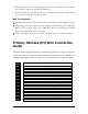
Shutdown Diagnostics The unit has the ability to report the cause of the last shutdown of the remote engine starting system. To enter diagnostic mode: 1. Turn the ignition off. 2. Press and HOLD the Valet/Program switch. 3. Turn the ignition on and then off. 4. Release the Valet/Program switch. 5. Press and release the Valet/Program switch. The LED status indicator will now report the last system shutdown by flashing for one minute in the following grouped patterns (see following table).
1. With the ignition off, press and HOLD the Valet/Program switch. 2. Turn on the ignition. 3. Release the Valet/Program switch. 4. Press and release the Valet/Program switch within 5 seconds. The LED status indicator will flash in groups indicating the last two zones that triggered the unit for one minute or until the ignition is turned off. NOTE: The Warning Zone triggers are not stored to memory and will not be reported.
a. b. c. d. e. Make sure the hood is closed and no other shutdown circuits are active. Set the emergency brake. Turn the ignition key to the run position but do not start the engine. Put the vehicle in Drive (D). Put your foot over the brake pedal but do not press down on it. Be ready to step on the brake to shutdown the remote engine starting system. f. Activate the remote engine starting system. ➤ If the starter engages, immediately step on the brake to shut down the system.
Closing the door triggers the system, but opening the door does not. ➤ Have you correctly identified the type of door switch system? This happens often when the wrong door input has been used. (See Door Lock Harness Wire Connection Guide section of this guide.) System will not passively arm until it is remotely armed and then disarmed. ➤ Are the door inputs connected? Is the H1/6 blue wire connected to the door trigger wire in the vehicle? Either the H1/5 green or the H1/7 violet should be used instead.
The remote engine starting will activate, but the starter never engages. 1. Check for voltage on the purple starter wire two seconds after the remote engine starting system becomes active. If there is voltage present, skip to Step 4. If there is not voltage present, advance to Step 2. 2. Check the 30A fuses. 3. Check diagnostics. If the gray/black wire is detecting ground upon activation, the starter will not crank. 4.
The vehicle will start, but will only run for 10 seconds. 1. Is the remote start programmed for voltage sense? Try programming the unit for low voltage reference. If this does not work, a tach wire should be used. 2. Check diagnostics. The climate control system does not work while the unit is operating the vehicle. ➤ Either the wrong accessory wire is being energized or more than one ignition or accessory wire must be energized in order to operate the climate control system.
Notes www.clifford.
Wiring Quick Reference Guide 48 © 2001 Directed Electronics, Inc.