
Installation guide

26 © 2000 Directed Electronics, Inc. Vista, CA
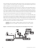
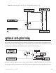
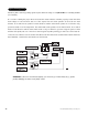
NOTE: A 1-amp diode (type IN4004) must be installed in line on the H2/1 blue status output (or
the H2/2 blue/black third ignition output wire) and the orange (-) ground-when-armed wire of the
starter kill relay. Insert diodes as shown in the diagram below.
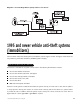
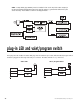
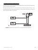
plug-in LED and valet/program switch
These plug into the module. The status LED plugs into the small two-pin socket, while the Valet®/Program switch
should be plugged into the larger blue two-pin connector. The status LED fits in a
9
/32-inch hole.
Status LED Valet®/Program Switch