
Manual

-4-
Operation(for customer)
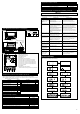
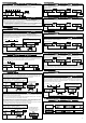
1.Set-Up Mode(Screen for setting units and display data parameters)
●Be sure to make preparatory settings. The unit will not operate properly without the settings being made.
●Set up while the vehicle is stationary.
Confirmation
When changing the factory settings shown below, pressing the SET UP(ENTER) button for more than 1 second after the
opening mode has completed will bring up the setting mode for units. In the set-up mode, the item to be set changes each
time SELECT▽ or BAR SELECT▲ buttons are pressed. When adjustment of a particular setting is needed, press the
ENTER button. To quit the the set-up mode, press the SET UP(ENTER) button for more than 1 second.
Press the ENTER button when the following figure is displayed. Use the
SELECT/BAR SELECT button to
select units
(kPa、℃、km/h or PSI、°F、MPH), then press the ENTER button to set the desired units.
Press
the
ENTER button when the following figure is displayed. Use
the
SELECT/BAR SELECT button to
select the speed pulse number, then press
the
ENTER button to set the selection.
②Setting of Speed Pulse②Setting of Speed Pulse
2 4 8 16 FREE(Free pulse setting)
<
Speed pulse number>
The speed pulse numbers differ by models of vehicles. Consult your local car dealer
if you are not certain of the speed pulse number for your vehicle.
<Free
pulse setting
>For vehicles having a speed pulse other than 2, 4, 8, or 16 pulse, the speed pulse can
be set by switching to the "FREE" screen by pressing and holding the ENTER button
for more than 2 seconds. After the screen changes to the pulse set screen(SET.P
blinks), press the ENTER button while the vehicle is moving at 60km/h or 40MPH.
※Ask fellow passengers to set up. Do not set up at the wheel.
※It may be unable to be adapted for some models of vehicles.
①Setting of Units ①Setting of Units
NOTE: The pulse free setting needs to be done again if unit systems are changed. When any of
numbers of speed pulse other than FREE is set after the pulse free setting is done, the pulse
free setting information is cleared.
Press the ENTER button while the vehicle is moving at 60km/h or 40MPH.
●Improper installation could cause the product to fall and damage the vehicle or cause serious danger by impeding driving.
・Attach the display unit in a location which will not hinder driving.
・Make sure that both the display unit and the D.C.Unit are firmly attached by using screws and double-sided tape.
●When installing the display unit, confirm the installation position with the customer and install it in a location which will
not hinder driving.
Warning
●Do not take off the rubber covering round the target screen. The plate is sharp-edged. Reapply the rubber when it
comes off.
Caution
●When leaving the car under the direct sunlight, cover the display unit with a white cloth. It prevents the unit from deterioration.
●Before attaching units using double-sided tapes, make sure the surfaces are clean.
●Do not expose the D.C.Unit and the Defi-Link Control Unit II(or the Defi-Link Control Unit) to direct sunlight.
●Do not touch the Target Screen. When it is stained with dust and finger marks, remove dust from the screen with adhesive
tape. And then wipe off with care by using a soft and dry cloth so as not to scratch it.
Confirmation
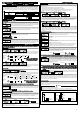
For D.C.Unit
Mounting
attachment
Mounting
bracket
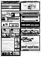
1) Tighten temporarily the mounting bracket to the mounting attachment with the bolt, nut,
and washer【Figure4】. Use a hexagonal Allen wrench to tighten the bolt. Then unfasten
screws of the mounting attachment until it rotates【Figure5】.
2) Turn on the ignition of the vehicle. Locate the display unit on the instrument panel while
looking at the reflecting image on the target screen. Adjust the angle and fix it by
combining with the mounting attachment and the mounting bracket. After the position is
located, mark it with adhesive tape. Turn off the ignition. (Refer to ③How to use the
mounting attachment and the mounting bracket and ④Installation examples of the
display unit.)
3) Fully tighten the screws of the mounting attachment【Figure5】.
4) Dismount the mounting bracket from the display unit, and then attach the double-sided
tapes on its undersurface. Bend it along the form of the instrument panel and fix it on
the panel with the tapping screws【Figure5】.
※Before attaching the unit using double-sided tapes, make sure the position is clean.
5) Connect the DIM sensor to the connector on the backside of the display unit.
6) Fit the display unit into the mounting bracket and tighten it fully with a hexagonal Allen
wrench.
7) Attach the DIM sensor to the side of display unit towards the direction of movement using
double-sided tape【Figure7-1】【Figure7-2】.
※Give attention to the attaching direction of the DIM sensor.
※Please fix the DIM sensor to the position in which the horizontal and forward
direction of the sensor is not interrupted with the wiper, and so on.
…3 for the D.C.Unit, 2 for the mounting bracket
…2 for the mounting bracket, 1 for the DIM sensor
After the installation is done, the next step is set-up the functions. Please refer to the backside of this
manual. The quick reference chart for the set-up is printed on the inside of the package.
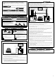
STEP3 Installation of Display Unit, DIM Sensor, and D.C.Unit
kPa、℃、km/h PSI、°F、MPH
Units setting
Speed pulse setting
① ② ③ ④ ⑤ ⑥ ⑦ ⑧ ⑨ ⑩ ⑪
Pulse free setting
Hold
Speed pulse setting
①Installation of D.C.Unit①Installation of D.C.Unit
Attach the D.C.Unit to a flat surface position such as a
center console and a DIN space. Before attaching the unit
using double-sided tapes, make sure the surface is clean.
The wires can be stored in
the storage space neatly.
②Best angle of the display unit②Best angle of the display unit
④Installation examples of the display unit④Installation examples of the display unit
③How to use mounting attachment and mounting bracket③How to use mounting attachment and mounting bracket
⑤Installation of the display unit and the DIM sensor⑤Installation of the display unit and the DIM sensor
⑥Example of installation⑥Example of installation
Bottom line of
the image
Adjust the angle of the display unit as follows:
Align the bottom of the reflected images to the line between the corners of
the Target Screen's both sides, when you see the display on the screen from
your driving position. The image is displayed most clearly at this angle.
※Confirm the angle and the attaching position of the display unit with the
driver.
【A】A place where the surface is downward toward the
windshield and downward toward the left side
【B】A place where the surface is downward toward the
driver's side
Left side view Bottom view
Driver's view
Left side view Bottom view
Driver's view
360° 40°
D.C.Unit
Defi-Link Control UnitⅡ
(or Defi-Link Control Unit)
Display unit
When attaching the display unit, the angle is adjusted and fixed by combining with the mounting attachment and the mounting bracket.
Mounting attachment・・・parts which is fastened on to the bottom of the display unit
Mounting bracket・・・fitting which is included in Mounting Bracket Set
The mounting attachment rotates by 360 degrees. The mounting bracket has a 40-degree range of movement.
Range of movement
【Figure4】Attach mounting bracket
with bolt
【Figure5】Loosen or tighten the screw of
mounting attachment
【Figure7-1】Fix DIM sensor
【Figure7-2】Installing direction of DIM sensor
【Figure6】Fix mounting bracket with
tapping screws
How to use double-sided tapes
OR
OR
OR
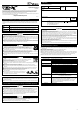
This illustration indicates positions of buttons for the Defi-Link Control Unit II
This illustration indicates positions of buttons for the D.C.Unit
Driver's seat
Driving direction
CommonCommon W/ LinkingW/ LinkingW/O LinkingW/O Linking
CommonCommon W/ LinkingW/ LinkingW/O LinkingW/O Linking
CommonCommon W/ LinkingW/ LinkingW/O LinkingW/O Linking
CommonCommon W/ LinkingW/ LinkingW/O LinkingW/O Linking
CommonCommon W/ LinkingW/ LinkingW/O LinkingW/O Linking
Item ItemFactory Default Factory Default
②Speed Pulse
③Number of Cylinders
④Warm-Up
⑤Special Display
⑥Tachometer Warning
①Units
4
4
Water Temp. 40℃(104°F)/
Oil Temp. 60℃(140°F)
Water Temp. 80℃(176°F)/
Oil Temp. 100℃(212°F)
ON
1→7000、2→8000
kPa、℃、km/h
ON
ON
Manual M-5(the brightest)
ON
⑦Bar Display
⑧Warning Buzzer
⑨Auto Warning
⑩Illumination Control
⑪Control Out