
Manual

-3-
【When the Defi-Link VSD X is used WITHOUT linking it to the Defi-Link System (W/O Linking)】
【When the Defi-Link VSD X is used WITH linking it to the Defi-Link System (W/ Linking)】
【Instructions which should be read in each case (Common)】
.
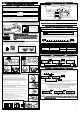
Tachometer signal wire(blue wire)
Power supply wire
Blue:Tacho signal
Engine control unit(ECU) or ignition primary coil
Green:Speed signal
2Pins
Blue:Tacho signal
Engine control unit(ECU) or ignition primary coil
Speed & tacho signal wire(6 3/5ft, 2m)【Figure2】 Tachometer signal wire(4 3/5ft, 2m)
※Use this wire only When Defi-Link VSD X is used
WITH linking to the Defi-Link System
【Figure3】
●Carefully read the "Before Installation" and "About Installation and Operation" sections of the manual concerning installation
and operation. Then install the product properly and safely. Installation in an unsuitable location or improper installation can
result in the product falling from its position or damage to the vehicle.
Installation (for installation personnel)
STEP1 Wiring power supply wire and signals
Warning
●When installing the display, be sure to follow the instructions of the Defi-Link Control Unit II(or the Defi-Link Control Unit).
●Do not pull the wires out of connectors forcefully. The
connectors may be broken and the wires may be cut.
When pulling out the wires, press the lock firmly and
unclip the locks of connectors.
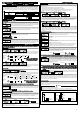
1) Connect the power supply wire to the vehicle with solderless connectors【Figure1】.
2) Connect the other side of the power supply wire to the DC SOURCE connector of the D.C.Unit.
※There are two DC SOURCE connectors. Both connectors are usable.
3) Connect the speed & tacho signal wire(green & blue wires) to the speed and tacho signal wire of the engine control
unit(ECU) with solderless connectors【Figure2】.
4) Connect the other side of the speed & tacho signal wire to the SPEED&TACHO connector of the D.C.Unit.
※In the case where this product is linked to the Defi-Link System afterward, connect the white wire of the power
supply wire to the illumination wire(12V wire when small lamp is on). Connect the tacho signal wire to the
Defi-Link Control Unit II(or the Defi-Link Control Unit【Figure3】.
1) Disconnect the previously connected power supply wire from the Defi-Link Control Unit II(or the Defi-Link Control Unit).
2) Connect the disconnected power supply wire to the DC SOURCE
connector
of the D.C.Unit.
※
There are two DC SOURCE connectors. Both connectors are usable.
3) Connect the DC SOURCE
connectors
of the Defi-Link Control Unit II(or the Defi-Link Control Unit) and the D.C.Unit
using the attached power supply link wire.
4) In the case where a meter wire is already connected to the METER OUTPUT1
connector
of the Defi-Link Control Unit
II(or the METER
connector
of the Defi-Link Control Unit), disconnect the meter wire. (If the METER OUTPUT1
connector of the Defi-Link Control Unit II is not in use, skip the next procedure and go to 6.)
5) Connect the disconnected meter wire to the LINK
connector
of the D.C.Unit.
※There are three LINK connectors. All three connectors are usable.
6) Connect the METER OUTPUT1
connector
of the Defi-Link Control Unit II and the LINK
connector
of the D.C.Unit using
the attached meter wire. (Connect the METER
connector
of the Defi-Link Control Unit and the LINK
connector
of the
D.C.Unit using the attached meter wire.)
※There are three LINK connectors. All three connectors are usable.
7) Connect the attached tachometer signal wire(blue) to the tacho signal wire of the engine control unit(ECU) using the
attached solderless connector. In the case where a tachometer signal wire(blue) is already connected to the D
efi-Link
Control Unit II(or
Defi-Link Control Unit), skip this procedure. Leave the tachometer signal wire(blue) and go to 9.
8) Connect the other side of the tachometer signal wire to the TACHO
connector
of the Defi-Link Control Unit II(or the Defi-
Link Control Unit).
※Be sure to connect the tachometer signal wire(blue) to the TACHO
connector
of the Defi-Link Control Unit II(or the
Defi-Link Control Unit). If the tachometer signal wire(blue) is connected to the D.C.Unit not to the Defi-Link Control
Unit II(or the Defi-Link Control Unit), the engine speed will not be displayed.
9) Connect the green wire of speed & tacho signal wire(speed signal) to the speed signal wire of engine control unit(ECU)
using the attached solderless connector.
※The blue wire of the speed & tacho signal wire does not need to be wired. Insulate and bind up the wire so as not to
interfere with driving
【Figure2】
.
10) Connect the other side of the speed & tacho signal wire to the SPEED&TACHO
connector
of the D.C.Unit.
Caution
STEP2 Check Wiring
1) Connect the display wire of the Defi-Link VSD X to the DISPLAY UNIT connector of the D.C.Unit.
2) Check that all the wires are properly connected.
3) Turn on the ignition of vehicle and make sure the display is lighted.(The display looks inverted on the display unit.)
4) If the display is lighted, go to the next step. If not, go back to STEP1 and rewire.
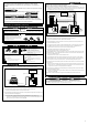
How to branch signal wire using solderless connector
wire from the vehicle
Insert wire of attached parts.
Press until a clicking sound is heard.
Defi-Link VSD X
D.C.Unit
Connect Defi-Link Meter BF to
METER OUTPUT2
Connect Defi-Link
Meter to LINK
Defi-Link Control Unit II
(or Defi-Link Control Unit)
Meter Wire(Connect METER OUTPUT1 and LINK)
Sensor wires
→to each sensors or vehicle
Power supply link wire(Connect DC SOURCEs mutually)
Speed & Tacho signal wire
Display unit's wire
■The following contents are classified into 3 categories. Please read the
necessary instructions and directions for use according to your situation as
follows:
■In the parts saying "Defi-Link Control Unit II," it applies to both the Defi-Link
Control Unit II(DF05001) and the Defi-Link Control Unit II Version 2.0(DF05002)
as long as any other special notes have not been described.
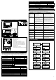
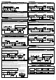
【Defi-Link VSD X wiring diagram
(When the Defi-Link VSD X is used WITHOUT linking it to the Defi-Link System)】
【Defi-Link VSD X and Defi-Link System wiring diagram
(When the Defi-Link VSD X is used WITH linking it to the Defi-Link System)】
D.C.Unit
DIM sensor
Power supply wire
Speed & tacho signal wire
Vehicle
(ECU, etc.)
Display unit's wire
Defi-Link VSD X
Display unit
DIM
Sensor
Vehicle
(ECU, etc.)
Defi-Link VSD X
Display unit
※Do not connect the blue
wire(tacho signal)
※Do not connect OUTPUT2 and LINK.
Blue wire(tacho signal)
Green wire(speed signal)
(Defi-Link Display is connectable)
(Defi-Link Display is
connectable.)
W/ LinkingW/ Linking
W/O LinkingW/O Linking
CommonCommon
W/ LinkingW/ Linking
W/O LinkingW/O Linking
W/ LinkingW/ Linking
CommonCommon
W/ LinkingW/ Linking
W/O LinkingW/O Linking
CommonCommon
W/ LinkingW/ Linking
W/O LinkingW/O Linking
CommonCommon
W/ LinkingW/ Linking
W/O LinkingW/O Linking
W/O LinkingW/O Linking
※These procedures are applicable on condition that Defi-Link Control Unit II(or Defi-Link Control Unit) and the
power supply wire have been installed. If the Defi-Link VSD X and the Defi-Link System are installed at the same
time, install the Defi-Link Control Unit II first by referring to the operation manual.
Fuse 4A
【Figure1】 Power supply wire(2 3/5ft, 80cm)
5Pins(1pin is vacant.)
Red:Battery(To 12V battery wire)
Black:GND(To ground, negative battery terminal)
White:+ILM(To 12V wire when small light is on)
Orange:IGN(To 12V wire when ignition is on)
※When this product is used without a connection to the
Defi-Link System, it is not necessary to connect the
white wire - insulate it.
※When connected to the Defi-Link System, do
not connect the blue wire - insulate it.
2Pins(1Pin is vacant.)
Connect to the Defi-Link Control Unit II(or Defi-Link
Control Unit)
※Do not connect to D.C.Unit.