
User Manual


80
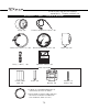
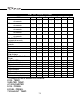
white color
black color
orange color
red color
unused
yellow color
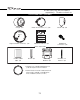
black color
white color
orange color
orange color
white color
black color
yellow color
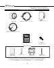
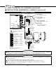
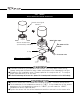
● INSTALLATION DIAGRAM(for installation personnel)
Installation diagram
Meter
Meter holder
Meter wire
Control Unit Ⅱ(rear view)
*DF05001:
black
Power supply wire
Huse 4A
Red : Battery
(To 12V battery wire)
Orange : IGN
(To 12V wire when
ignition on)
White : Illumination
(To 12V wire when small
lamp is on)
Black : GND
(To ground, negative
battery terminal)
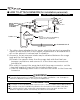
●
Please read the safety warnings thoroughly for the installation and handling. Improper
installation or operation could cause the product to fall and damage the vehicle.
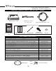
Control Unit Ⅱ
Sensor wire connections
position
CAUTION
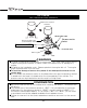
M-WARNING (white)
TACHOMETER (white)
WATER TEMP. (blue)
EXHAUST TEMP.
(black)
OIL TEMP. (white)
FUEL PRESS. (blue)
OIL PRESS. (black)
(white)
DC SOURCE (white)
METER OUTPUT
1(white)
METER OUTPUT
2(white*)
●Insert the wire that matches the wire connections position indicated on the side of
the control unit.
The unit will not function with incorrect connections.
●Pull out each connector with pressing the lock of the connector firmly.
●Put the connector of INTAKE MANIFOLD PRESS’s sensor wire in TURBO
connector(white) of Control Unit Ⅱ.
WARNING
TURBO(BOOST)/
INTAKE MANIFOLD PRESS.
Defi-Link
Meter
Defi-Link
Meter BF
6.HOW TO INSTALL(for installation personnel)