日本国内でご購入の場合は1ページから54ページをお読みください。 切 り 取 り 線 このたびは、当社製品をお買い上げいただきまして、誠にありがとうござ います。ご使用の前に本書を必ずお読みいただくとともに常にお手元に 保管いただき、正しいお取り扱い方法でご愛用いただけますようお願い 申し上げます。なお、本品の装着に関する事故や弊害につきましては、 いかなる場合においても、当社は一切責任を負いかねますので、あらか じめご了承いただけますようお願い申し上げます。 ※英語の部分は国内では無効です。 【Webサイト】http://www.nippon-seiki.co.jp/defi/ 【電話番号】 (03)3835-3639(Japanese only) 【受付時間】10:00∼12:00, 13:00∼17:00 (土・日、祭日、当社休日を除く平日) English section is from P.55 to P.110. Thank you very much for purchasing our product.
Contents 1.Safety Warning ‥‥‥‥‥‥‥‥‥‥‥‥‥‥‥‥‥‥‥‥‥P56∼60 2.Main Product Features ‥‥‥‥‥‥‥‥‥‥‥‥‥‥‥‥‥P61∼64 3.The list of Defi-Link System ‥‥‥‥‥‥‥‥‥‥‥‥‥‥‥P65・66 4.Specification ‥‥‥‥‥‥‥‥‥‥‥‥‥‥‥‥‥‥‥‥‥‥‥‥‥P67 5.Product Parts ‥‥‥‥‥‥‥‥‥‥‥‥‥‥‥‥‥‥‥‥‥‥P68∼78 Optional Parts List ‥‥‥‥‥‥‥‥‥‥‥‥‥‥‥‥‥‥‥‥‥‥P78 List of tools to use ‥ ‥‥‥‥‥‥‥‥‥‥‥‥‥‥‥‥‥‥‥‥‥P79 6.How to Install ・ Installation diagram ‥‥‥‥‥‥‥‥‥‥‥‥‥‥‥‥‥‥‥‥P80 ・ How to attach sensors ‥‥‥‥‥‥‥‥‥‥‥‥‥‥‥‥P81∼88 ・ Wiring the Control Unit Ⅱ ‥‥‥‥‥‥‥‥‥‥‥‥‥‥‥‥‥P89 ・ How to atta
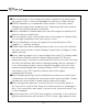
Please be sure to read this manual carefully before attempting to install or operate this product. 1.SAFETY WARNING Please read carefully, where the " WARNING " and " CAUTION "symbols are displayed in this manual. Failure to do so may result in damage or injury. WARNING Indicates the possibility of death or serious injury in the event of incorrect installation. CAUTION Indicates a risk of personal injury or damage to equipment in the event of incorrect installation.
●The components of the product should be installed in a place where they can not fall or move and damage the vehicle or hinder driving. ●NEVER dismantle or re-assemble the products. This could cause damage and make them unsafe to use. Tampering with the products renders the limited warranty ineffective. ●Before installation, please make sure that the engine is switched off and the vehicle is stationary.
(more than 30A) will not blowout even with an abnormal current flow and may cause fire. CAUTION ●This product is for use ONLY on vehicles with a 12V electrical system. NEVER use the product on 24V vehicles. ●Use only the wires provided. If additional wires are required, use the same of quality and gauge wire as is provided with the kit. ●Insulate any unused wires. If any wires or connectors loosen during installation, please make sure they are correctly reattached.
CONFIRMATION ●Gauge pointer may not be in the proper position when you purchase. Normal function will resume when power is connected. ●Please read pages for the customer as well as the pages for the installation personnel in order to have a full understanding of all the procedures. ●Please confirm with the maintenance book on the car that the manufacturer issued when installing and detaching genuine parts.
CONFIRMATION ●Do not set the number of cylinders when TACHOMETER is not installed. *Please pull out each connector while pressing the lock of the connector firmly.
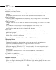
2.MAIN PRODUCT FEATURES (for customer) Defi-Link Meter Indicator To Power Source To sensor METER OUTPUT 1 (M-WARNING) Control Unit Ⅱ Defi-Link Meter BF Indicator 61 METER OUTPUT 2
Daisy Chain Connection a)Multiple Interface System Uses only one wire to send power, light, ground, and data to and from all seven gauges. All gauges and the Control Unit Ⅱ have separate microcomputer units. b)Easy installation Installing additional gauges involves simply connecting them to the installed gauge and wiring the sensor to the Control Unit Ⅱ. c)Easy operation Gauges that are out of reach can be controlled by using the Control Unit Ⅱ at hand.
b)Wiring check function Any cut wire, short circuit, and communication errors are checked and possible areas of fault are checked. c)Warning function A warning value can be set. When this value is exceeded, a red warning LED comes on. It is possible to connect a Defi-Link Indicator(sold separately). d)Peak memory function Peak values are stored and can be checked later. 3.Attractive design a)A mounting bracket and instrument case is provided with the product.
Features of Defi-Link Meter a)A bright transparent green gauge dial and a red instrument needle pointer are used in the gauges to increase visibility at night and in low-light applications. Features of Defi-Link Control Unit Ⅱ a)Up to 7 gauges from among Defi-Link Meter BFs and Defi-Link Meters can be operated with one Control Unit Ⅱ. Microcomputers are equipped with meters and Control Unit Ⅱ. A distant meter can be operated at hand.
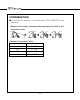
3.The list of Defi-Link System Defi-Link Meter BF Size 60mm Product Name Illumination Color White TURBO Amber Red White OIL PRESS. Amber Red White FUEL PRESS. Amber Red White OIL TEMP. Amber Red White WATER TEMP. Amber Red White EXHAUST TEMP. Amber Red INTAKE MANIFOLD White PRESS.
Defi-Link Meter Size Product Name Defi-Link Meter TURBO Defi-Link Meter OIL PRESS. Defi-Link Meter FUEL PRESS. 52mm Defi-Link Meter OIL TEMP. Defi-Link Meter WATER TEMP. Defi-Link Meter EXHAUST TEMP. Defi-Link Meter INTAKE MANIFOLD PRESS.
4.Specification Power Supply Voltage DC10V∼15V(For 12V vehicles) Current Consumption (Maximum value in case 7 gauges are connected to the Defi-Link Control Unit Ⅱ +B line MAX 2A (Dark current MAX 2.5mA) IGN line MAX 0.1A ILM line MAX 0.2A Operational Temperature Range -20 ∼ +60℃, -4 ∼ +140° F (under 80% relative humidity) Storage Temperature Range -40 ∼ +80℃, -40 ∼ +176° F (under 80% relative humidity) Display Range Turbo -100kPa ∼ +200kPa Intake Manifold Press. -100kPa ∼ +20kPa Oil Press.
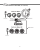
*Each part can be purchased separately. Please contact us. 5.PRODUCT PARTS TURBO (52mm & 60mm & 80mm) INTAKE MANIFOLD PRESS. (52mm & 60mm) White 3pins Gauge 1pc Boost sensor 2.5m(8 1/5ft.)1pc Rubber hose 0.5m (1 3/5ft.
*Each part can be purchased separately. Please contact us. TURBO(115mm) White 3pins Gauge 1pc Boost sensor 2.5m (8 1/5ft.)1pc Meter wire 0.25m (10") 1pc Three way joint 1pc Rubber hose 0.5m (1 3/5ft.
*Each part can be purchased separately. Please contact us. OIL PRESS.(52mm & 60mm) * After the oil pressure sensor is connected, a buzzer sounds when the ignition switch is turned on but the engine is not started. Gauge 1pc * Pressure sensor 1pc Meter wire 0.
*Each part can be purchased separately. Please contact us. FUEL PRESS.(52mm & 60mm) Pressure sensor 1pc Gauge 1pc Meter wire 0.25m (10") 1pc Meter cup 1pc Blue 3pins 日本国 内でご 購入の 場合は 1ペー ジから 54ペ ージを お読み くださ い。 このたびは、当社製品をお買い上げいただきまして、誠にありがとうござ います。 ご使用 の前に 本書を 必ずお 読みい ただく ととも に常に お手元 に 保管い ただき 、正し いお取 り扱い 方法で ご愛用 いただ けます ようお 願い 申し 上げ ます 。な お、 本品 の装 着に 関す る事 故や 弊害 につ きま して は、 いかな る場合 におい ても、 当社は 一切責 任を負 いかね ますの で、あ らか じめご了承いただけますようお願い申し上げます。 ※英語の部分は国内では無効です。 【Webサイト】http://www.nippon-seiki.co.
*Each part can be purchased separately. Please contact us. OIL TEMP.(52mm & 60mm) Gauge 1pc Temperature sensor 1pc Meter wire 0.25m (10") 1pc Meter cup 1pc White 2pins 日本国 内でご 購入の 場合は 1ペー ジから 54ペ ージを お読み くださ い。 このたびは、当社製品をお買い上げいただきまして、誠にありがとうござ います。 ご使用 の前に 本書を 必ずお 読みい ただく ととも に常に お手元 に 保管い ただき 、正し いお取 り扱い 方法で ご愛用 いただ けます ようお 願い 申し 上げ ます 。な お、 本品 の装 着に 関す る事 故や 弊害 につ きま して は、 いかな る場合 におい ても、 当社は 一切責 任を負 いかね ますの で、あ らか じめご了承いただけますようお願い申し上げます。 ※英語の部分は国内では無効です。 【Webサイト】http://www.nippon-seiki.co.
*Each part can be purchased separately. Please contact us. WATER TEMP.(52mm & 60mm) Gauge 1pc Temperature sensor 1pc Meter cup 1pc Meter wire 0.25m (10") 1pc Blue 2pins 日本国 内でご 購入の 場合は 1ペー ジから 54ペ ージを お読み くださ い。 このたびは、当社製品をお買い上げいただきまして、誠にありがとうござ います。 ご使用 の前に 本書を 必ずお 読みい ただく ととも に常に お手元 に 保管い ただき 、正し いお取 り扱い 方法で ご愛用 いただ けます ようお 願い 申し 上げ ます 。な お、 本品 の装 着に 関す る事 故や 弊害 につ きま して は、 いかな る場合 におい ても、 当社は 一切責 任を負 いかね ますの で、あ らか じめご了承いただけますようお願い申し上げます。 ※英語の部分は国内では無効です。 【Webサイト】http://www.nippon-seiki.co.
*Each part can be purchased separately. Please contact us. EXHAUST TEMP.(52mm & 60mm) Gauge 1pc Exhaust temperature sensor 1pc Black 2pins Meter wire 0.25m (10") 1pc Sensor wire 2.5m (8 1/5ft.
*Each part can be purchased separately. Please contact us. TACHOMETER(60mm) Gauge 1pc Meter wire 0.25m (10") 1pc White 2pins Meter cup 1pc 日本国 内でご 購入の 場合は 1ペー ジから 54ペ ージを お読み くださ い。 このたびは、当社製品をお買い上げいただきまして、誠にありがとうござ います。 ご使用 の前に 本書を 必ずお 読みい ただく ととも に常に お手元 に 保管い ただき 、正し いお取 り扱い 方法で ご愛用 いただ けます ようお 願い 申し 上げ ます 。な お、 本品 の装 着に 関す る事 故や 弊害 につ きま して は、 いかな る場合 におい ても、 当社は 一切責 任を負 いかね ますの で、あ らか じめご了承いただけますようお願い申し上げます。 ※英語の部分は国内では無効です。 【Webサイト】http://www.nippon-seiki.co.jp/defi/ 【Eメール】defi@nippon-seiki.co.
*Each part can be purchased separately. Please contact us. TACHOMETER(80mm) Gauge 1pc Meter wire 0.25m (10") 1pc Meter cup 1pc White 2pins Signal wire 2m (6 3/5ft.) 1pc 日本国 内でご 購入の 場合は 1ペー ジから 54ペ ージを お読み くださ い。 このたびは、当社製品をお買い上げいただきまして、誠にありがとうござ います。 ご使用 の前に 本書を 必ずお 読みい ただく ととも に常に お手元 に 保管い ただき 、正し いお取 り扱い 方法で ご愛用 いただ けます ようお 願い 申し 上げ ます 。な お、 本品 の装 着に 関す る事 故や 弊害 につ きま して は、 いかな る場合 におい ても、 当社は 一切責 任を負 いかね ますの で、あ らか じめご了承いただけますようお願い申し上げます。 ※英語の部分は国内では無効です。 【Webサイト】http://www.nippon-seiki.co.
*Each part can be purchased separately. Please contact us. TACHOMETER(115mm) Gauge 1pc Meter wire 0.25m (10") 1pc White 2pins Meter cup 1pc Signal wire 2m (6 3/5ft.) 1pc 日本国 内でご 購入の 場合は 1ペー ジから 54ペ ージを お読み くださ い。 このたびは、当社製品をお買い上げいただきまして、誠にありがとうござ います。 ご使用 の前に 本書を 必ずお 読みい ただく ととも に常に お手元 に 保管い ただき 、正し いお取 り扱い 方法で ご愛用 いただ けます ようお 願い 申し 上げ ます 。な お、 本品 の装 着に 関す る事 故や 弊害 につ きま して は、 いかな る場合 におい ても、 当社は 一切責 任を負 いかね ますの で、あ らか じめご了承いただけますようお願い申し上げます。 ※英語の部分は国内では無効です。 【Webサイト】http://www.nippon-seiki.co.
*Each part can be purchased separately. Please contact us. Defi-Link Control Unit Ⅱ(52, 60, 80, 115mm) Control Unit Ⅱ 1pc Power wire 0.75m (2 1/2ft.) 1pc Meter wire 2m(6 3/5ft.
LIST OF TOOLS TO USE TOOL 10mm spanner or wrench 12mm spanner or wrench 14mm spanner or wrench 17mm spanner or wrench 20mm spanner or wrench 52, 60, 80mm hexagonal wrench 115mm hexagonal wrench Tester Extension wire Plyers Wiring cutters/ Side cutters Phillips & Flat Blade Screw Driver 1/8 drill NPT tap Solder and solder iron Clipped end wiring Vinyl tape T-Bolt clamps Teflon tape 8.
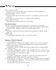
6.HOW TO INSTALL(for installation personnel) ● INSTALLATION DIAGRAM(for installation personnel) Installation diagram Power supply wire Huse 4A Red : Battery (To 12V battery wire) Orange : IGN (To 12V wire when ignition on) white color black color orange color red color unused Defi-Link Meter Defi-Link Meter BF White : Illumination (To 12V wire when small lamp is on) Black : GND (To ground, negative battery terminal) orange color white color black color yellow color Control Unit Ⅱ Sensor wire connectio
● HOW TO ATTACH SENSORS(for installation personnel) TURBO Attach with clamps. (commercially available) INTAKE MANIFOLD PRESS. (a) (c) Three-way joint Surge tank (b) Fuel regulator Rubber hose Sensor *Be sure to be installed being faced the air hole down. →To Control Unit Ⅱ Sensor wire 1. The rubber hose attached to the sensor should be as short as possible. Attach it with bolts (M6) in the engine compartment in an area where it will not be subject to excess heat or vibration. 2.
OIL PRESS. Use a commercial sensor attachment Detach the original element Wind Teflon tape. Engine Be sure not to twist. Sensor attachment (commercially available) Thread size 1/8PT O ring → To sensor wire Sensor Engine WARNING ●To avoid oil leaks during installation of the sensors, use Teflon tape. Before driving, inspect tubing and oil blocks for leaks. Leaks could cause a fire or damage the engine. ●Oil spills by the installation work. Please replenish the engine with oil.
OIL TEMP. Use a commercial sensor attachment Detach the original element Engine Wind Teflon tape. Sensor attachment (commercially available) Be sure not to twist. Sensor O ring → To sensor wire Thread size 1/8PT Engine WARNING ●To avoid oil leaks during installation of the sensors, use Teflon tape. Before driving, inspect tubing and oil blocks for leaks. Leaks could cause a fire or damage the engine. ●Oil spills by the installation work. Please replenish the engine with oil.
WATER TEMP. Use a commercial sensor attachment Radiator Upper hose Sensor attachment (commercially available) Attach tightly with clamps. (commercially available) Thread size 1/8PT Wind Teflon tape. Sensor *Cut the upper hose and connect the sensor attachment between hoses. Be sure not to twist. To sensor wire← WARNING ●To avoid water leaks during installation of the sensors, use teflon tape. Attach the T-joint and upper hose with a T-Bolt clamp. Inspect hose connections for leaks before driving.
FUEL PRESS. Use a commercial three-way joint and hose unions Fuel pressure regulator Wind Teflon tape. To sensor wire ↑ Hose union (commercially available) Three-way joint (commercially available) Fix tightly with clamps. (commercially available) Be sure not to twist. Sensor *Cut the fuel feed pipe and install hose unions. Thread size 1/8PT Fuel return pipe (low pressure) Fuel feed pipe(high pressure) WARNING ●To avoid fuel leaks during installation of the sensors, use Teflon tape.
EXHAUST TEMP. Exhaust manifold 2 pin plug Sensor wire → To Control Unit Ⅱ Sensor Attach here. Fitting(1/8PT) (1/8NPT Fitting is an optional part.) 1.Dismantle the sensor fitting(making sure not to crush the bushing inside the fitting) . Attach the sensor fitting at the point where the screw threw thread is hashed using the 1/8PT tap. 2.Pass the sensor through the bushing and fitting nut and attach the sensor fitting to the exhaust manifold.
TACHOMETER(Only for Defi-Link Meter) 1.HOW TO SET THE NUMBER OF CYLINDERS Use the cylinder switch at the back of the Control Unit II to set up the number of cylinders according to your vehicle. When the number of cylinders is set other than 1, 2, 3, 4, 5, 6, or 8, the tachometer carries out the same operation as the short circuit check function.
TACHOMETER 2.HOW TO ATTACH THE SIGNAL WIRE *Please consult your local car dealer for the place of Engine Computer Unit(ECU) and the place of the engine revolution signal. Solderless connector Tachometer Signal wire Control Unit Ⅱ ECU (Engine Computer Unit) CAUTION ●Before tapping engine rev signal cable, please make sure that you have disconnected the negative (-) cable from the negative terminal of the battery. If any battery line is live, there is a risk of destroying the ignition coils or ECU.
● WIRING THE CONTROL UNIT Ⅱ(for installation personnel) ○HOW TO SOLDER (1)Strip off the outer wire insulating (2)Wind to fasten the peeled wire (3)Solder this part, making sure it is spread property (4)Wrap tightly with vinyl tape ○HOW TO USE THE SOLDERLESS CONNECTOR Red : Battery (To 12V battery wire) Orange : IGN (To 12V wire when ignition on) Power supply wire White : Illumination (To 12V wire when small lamp is on) Black : GND (To ground, negative battery terminal) wire from vehicle vehicle side
●HOW TO ATTACH THE CONTROL UNIT Ⅱ(for installation personnel) ・Control Unit Ⅱ is a half DIN sized. It can be put in a DIN space of center console neatly. ・Attach double sided tapes on the Control Unit Ⅱsurface. Place the Control Unit Ⅱ on a flat surface of the center console. CONFIRMATION ●Use appropriate dashboard cleaning liquids (commercially available) to clean the area in which the double sided tape will be attached.
●HOW TO INSTALL METERS (for installation personnel) (A) 52mm, 60mm, 80mm meters, meter cup and meter cup holder 【figure 2】 【figure 1】 【figure 3】 buffer 【figure 4】 Leave a space from 2 to 5 mm Double sided tape b Mounting bracket (rear side) 1.Cut the double sided tape as shown in figure 1. 2.Insert convex part of the mounting bracket over the legs of the meter cup. Attach the mounting bracket to the meter cup with the nut and bolt included in the kit as shown in figure 2. 3.
(B) Bezel (52mm and 60mm meter) ・The red triangle can be used as an warning indicator. ・To move the position of the red triangle, remove the bezel once and then attach it again. ・Some kinds of meter hoods and visor cannot be installed in combination with the bezel. (Refer to P.67) (C) 115mm meter 【figure 1】 Buffer 【figure 2】 Bolt for Meter cup 1.Insert the convex part of the mounting bracket over the legs of the meter cup.
●How to attach optional parts (for installation personnel and customer) (The meter cup and the meter cup holder are not supplied with the following parts) (A)Single Meter Visor (for 60mm meters) This item is for removing a virtual image of a meter reflected on a windshield. It is easy to attach: put the Single Meter Visor between a meter and a meter cup. ・Single Meter Visor cannot be attached with the bezel.
(C)Defi-Link Indicator *When installing and using the Defi-Link Indicator Ⅱ, please refer to its operation manual. ・In the case of the use as an indicator for each meter 1. Attach double-sided tape on the bottom of the indicator. (Use two sheets of doublesided tape for a 80mm or 115mm meter.) 2. Connect the indicator wire to the body of the indicator. (Use one of two wires that matches your desirable installation.) 3. Attach the indicator to a meter or the instrument panel.
●FINAL CONFIRMATION AFTER INSTALLATION(for installation personnel) WARNING ●Please be sure to check the following items. Otherwise, there is a possibility that a serious accident may occur. ○Ensure that all hoses and tubing are permanently attached. Also ensure that there is no leakage of oil, fuel, water and exhaust. ○Check that the sensor and wires are not interfering with the engine. ○Ensure that devices associated with the ignition(ie. ignition coil, distributor, plug cord, etc.
7.OPERATION(for customer) Please read and understand the following before operating this instrument.
(B)Mode 「REAL MODE」 The pointer displays the actual vehicle condition in real time. At the same time, the PEAK value is stored in memory inside the Control Unit Ⅱ. Control Unit Ⅱ 「PEAK MODE」 If the Control Unit Ⅱ PEAK switch is pressed for less than 2 seconds, the PEAK LED is illuminated. This indicates PEAK MODE. In PEAK MODE(PEAK LED is illuminated), all meter pointers will display PEAK values simultaneously. The Control Unit Ⅱ records any new PEAK values as they occur.
Control Unit Ⅱ 「WARNING SET MODE」 If the Control Unit Ⅱ WARN SET switch is pressed, WARNING LEDs of all gauges will blink all at once. This is the warning set mode. The LED of gauge to be set will flash quickly. *WARNING values of each gauge can be set by pressing UP/DOWN switches. *The pointer will move faster by pressing the UP/DOWN switches for a long period. Every time the WARN SET switch is pressed, the gauge to be set up changes.
「WARNING MODE」 If the meter exceeds the value set for warning, the WARNING LED(red) goes on and a buzzer sounds. If the pointer turns back lower than the set value, the LED goes off. WARNING LED(red) *The WARNING LED (red) will go on at values lower than the set value in the cases of OIL PRESS. meter and FUEL PRESS. meter. *After the oil pressure sensor is connected, a buzzer sounds when the ignition switch is turned on and the engine is not started.
Control Unit Ⅱ 「RECORD MODE」 ・ 「PLAYBACK MODE」 Driving data is recorded and played up to 3 minutes. 「RECORD MODE」 By pressing the Control Unit Ⅱ REC switch, PEAK LEDs of all connected meters flash at the same interval and driving data is recorded up to 3 minutes. flashing interval PEAK LED constant interval flash After 3 minutes PEAK LEDs stop flashing after 3 minutes have gone by. Then meters return to REAL MODE. To stop recording before 3 minutes have passed, press REC switch again.
Control Unit Ⅱ 「PLAYBACK MODE」 By pressing the Control Unit Ⅱ PLAY switch, PEAK LEDs of all connected meters flash at the same interval and recorded driving data is played. Playback is paused if UP switch or DOWN switch is pressed for a short period (within 0.5 seconds) during playback. During pause, the PEAK LED flashes at a different interval from the interval of playback.
「DIFFERENTIAL PRESSURE MODE」 If both of the fuel pressure meter and turbo meter are installed, DIFFERENTIAL PRESSURE LED comes on by pressing the UP switch and the DOWN switch at the same time. This indicates DIFFERENTIAL PRESSURE MODE. In this mode, the fuel pressure meter indicates the pressure value which is the intake manifold pressure value subtracted from the fuel pressure value. Control Unit Ⅱ If the UP switch and the DOWN switch are pressed at the same time, meters return to REAL MODE.
「REAL MODE」 Control Unit Ⅱ 「ILLUMINATION FUNCTION」 Only for Defi-Link Meter BF In REAL MODE, the brightness of illumination can be adjusted by pressing the UP switch or DOWN switch. There are 5 stages of brightness in the daytime and 5 stages in the nighttime. The brightness decreases with being interlocked with the illumination switch on. If the UP switch is pressed several times in the nighttime, the brightness will become the highest stage of the daytime brightness.
(C)CHECK FUNCTIONS (for installation personnel and customer) WARNING ●Please check meters after starting the engine and be sure there are no abnormalities in the car. If you start to drive without checking, serious accidents may occur. Control Unit Ⅱ checks the pointer movement and the illumination of meters. 「WIRE DISCONNECTION CHECK」 This function reports the wrong wiring and/or disconnected sensors and wires. The pointer points downwards and the WARNING LED flashes.
「SERIAL ERROR CHECK」 This function reports that communication is impossible between meters and Control Unit Ⅱ. The pointer points downwards and the WARNING LED flashes twice at the same interval. LED flashes twice at same interval 「OPENING MODE」 The pointers of 115mm (4 1/2” ) meters move faster than that of smaller meters.
8.TROUBLE SHOOTING (for customer and installation personnel) WARNING When abnormal conditions are found in meters, please be sure to check. Otherwise, serious accidents may occur. Please refer to the table below and reconfirm before asking for repairs. CONDITION POSSIBLE CAUSE REMEDY ・In general the gauges show low values. ・ The gauges don't perform the opening mode. ・The earth wire is not properly fixed on the battery minus terminal. ・A harness wire is not installed properly.
CONDITION POSSIBLE CAUSE REMEDY ・Illumination of Defi-Link Meters doesn't go out being interlocked with the illumination switch off. ・Defi-Link Meters are connected to METER OUTPUT2. ・Connect Defi-Link Meters to METER OUTPUT1. ・Brightness of Defi-Link Meter BF's illumination can not be adjusted. ・Illumination of Defi-Link Meter BF doesn't go on. ・Defi-Link Meter BFs are connected to METER OUTPUT1. ・Connect Defi-Link Meters to METER OUTPUT2.
9.Terms and Conditions 1. LIMITED PRODUCT WARRANTYAND LIMITED PRODUCT LIABILITY A Limited Warranty a. Our sole obligation to you after the sale of a product is to replace, without charge, the product or any component thereof discovered to be defective within a period of one (1) year from the purchasing date (the "Warranty Period"). You accept sole responsibility for the proper assembly, operation and regular maintenance of the product.
OR CONSEQUENTIAL DAMAGES ARISING OUT OF OR IN CONNECTION WITH YOUR USE OF THE PRODUCT. f. The warranty on this product is void if the product is modified, changed, adjusted or damaged. This product is to be used only in the ways for which it is designed and marketed for, any deviations from the intended uses will void the warranty and will excuse any possible liability of ours. g. You accept sole responsibility for the proper assembly, operation and regular maintenance of the product.
or accessories in connection with the installation and use of the product that are not authorized and approved by us. C Indemnity and Release a. You understand and agree that many factors beyond our control affect the operational safety of the product, including but not to limited to the installation of the product according to the instructions provided with the product. b.