デフィーリンクアドバンスコントロールユニット取扱説明書 Defi-Link ADVANCE Control Unit Operation Manual DF07703 日本国内でご購入の場合は 2 ページから 40 ページをお読みください。 このたびは、当社製品をお買い上げいただきまして、誠にありがとうご ざいます。お客様・取付業者様ともに、ご使用の前に本書を全て必ずお読 みいただき、取付後も常にお手元に保管し、正しいお取り扱い方法でご愛 用いただけますようお願い申し上げます。 なお、本品の装着に関する事故や弊害につきましては、いかなる場合に おいても、当社は一切責任を負いかねますので、あらかじめご了承いただ けますようお願い申し上げます。 ※英語の部分は国内では無効です。 【Web サイト】http://www.nippon-seiki.co.jp/defi/ 【電話番号】(03)3835-3639 【受付時間】10:00 ~ 12:00、13:00 ~ 17:00( 土・日、祭日、当社休日を除く平日 ) English section is from P.41to P.83.
もくじ Contents もくじ Contents・ ・・・・・・・・・・・・・・・・・・ 1 1安全・取り扱いに関するご注意【必ずお読みください】・・ 2 2特長・・・・・・・・・・・・・・・・・・・・・・・・ 8 3ラインナップ・価格・・・・・・・・・・・・・・・・・ 8 4仕様・・・・・・・・・・・・・・・・・・・・・・・・ 10 5構成部品・各部名称・寸法・・・・・・・・・・・・・・ 11 6取付方法・・・・・・・・・・・・・・・・・・・・・・ 14 7使用方法・・・・・・・・・・・・・・・・・・・・・・ 21 8トラブルシューティング・・・・・・・・・・・・・・・ 34 9補修パーツ・オプションパーツ ・ ・・・・・・・・・・・ 37 保守・点検・保証・アフターサービス・・・・・・・・・ 38 1 Safety Warning 【Please read carefully.
1 Safety Warning 【Please read carefully.】 This product is a required for ADVANCE gauges and displays. This product alone does not operate. Please use this product with ADVANCE gauges or displays. As for installation and operation, please refer to the manual for the gauges and displays as well. This product is an additional product for providing information to automobile users about engine conditions and other important factors.
■ Before handling (for installation personnel) Danger Ensure that the vehicle will remain stationary and turn off the engine before installing this product. Failure to do so could result in a fire, and could make the vehicle move during installation. Remove the key from the ignition and disconnect the negative (-) battery terminal prior to installation of this product. Failure to do so could result in a fire caused by an electrical short circuit.
Warning Carefully consider the installation location and driver's operation of the product before installation. Do not install the product where it interrupts driving and the safety deices of vehicle such as air bags. Be sure not to install the unit where it could fall. Improper installation or operation could cause the product to fall and damage the vehicle or cause serious danger by impeding driving. Do not disassemble or modify this product.
Do not apply excessive force on switches/terminals. It may result in damage to the product. Do not use wires other than the provided wires. Do not attach wires on the body of the vehicle or engine parts as this may result in damage to the product. Install wires away from ignition and also radio signal frequency interference as this could cause the gauges to malfunction.
Confirmation Be sure to follow all instructions in this manual to ensure safe installation and operation of the product. When the negative (-) battery terminal is disconnected, equipment such as clocks and audio components having internal memory may lose their memory data. Follow the operation manual of each component to reset data after installation of this product. After installation is complete, return this operation manual, warranty card, and the package along with the warranty to the customer .
Discontinue use of this product if the gauge doesn't operate, water gets into the unit, or smoke or a strange odor comes from the unit. If such a condition occurs, contact the store or installation personnel as soon as possible. Continued use while the condition exists could result in an accident or fire. Do not operate while driving. Fix the switch unit and other parts tightly to the vehicle to avoid children's accidentally swallowing them. Do not use the TIME ATTACK function of ADVANCE ZD in open roads.
2 Product Features Interactive communication advanced system is implemented. Up to 7 ADVANCE gauges and displays in all can be controlled. Gauges can be controlled from distance with the included switch unit. The illumination color is white. By connecting ADVANCE ZD to the ADVANCE system, the illumination of ADVANCE BF and CR gauges is controlled automatically. Opening and ending modes can be selected from 2 variations. The installation of additional gauges is easy.
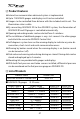
■ ADVANCE CR gauges Product name Turbo2.0 Turbo1.
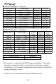
4 Specification ■ Power supply voltage 10V ~ 16V DC(For 12V vehicle) ■ Current Consumption Maximum value in case 7 gauges or displays are connected +B line ILM line ■ Illumination color 2A(IGN ON) 5mA(IGN OFF) 800mA Control Unit DC Source LED:blue.
5 Parts List/Part Names/Dimensions 5 -1. Parts List ADVANCE Control unit 1pc Switch unit Wire1.5m(5ft) 1pc Power source wire 1m(3 1/3ft.) 1pc Meter wire 2m(6 3/5ft.) 1pc Accessories Double sided tape 1pc Clip 1pc Tie wrap Nut 2pcs 4pcs Solderless connector 4pcs Bolt 4pcs Operation manual (this booklet) and warranty card are included with the parts listed above.
5 -2. Part Names & Dimensions of Control Unit in mm(inches) Screw holes(4 places) ② ③④ ⑤ ⑥ ⑦ ⑧ ⑨ ⑩ ⑪ 22(2.05") 153.2(6.03") Dip switch 26.3(1.04") 51(2") 104(4.1") ① 15(0.
5 -3. Part Names & Dimensions of Switch unit in mm(inches) 80(3.15") 78.4(3.09") 16(0.63") 26.2(1.03") 7(0.28") Differential pres- Left button Right button Slide switch sure LED(blue) (REAL/PLAY/SET from the top) Middle button ● Backside of switch unit Lot No. label Do not peel the labels sticked on the product and warranty card. Applying position of double-sided tape ● Buttons and slide switch Operation of gauges is handled by 3 buttons and 1 slide switch.
6 Installation Confirmation Please refer to how to install gauges, displays, and sensors of each manual as well as this manual. 6 -1. Installation diagram Switch unit Sensor Wires →Sensors →Connect to vehicle Power source wire →Connect to vehicle Meter wire Meter wire ADVANCE Control Unit CR ZD BF CR ZD BF CR The meter wire can be connected to both two connectors of METER OUTPUT. Up to 7 gauges and displays in all can be connected to one control unit. (Ex.
6 -2. Procedure 1. Confirm the contents. ⇒ Please refer to operation manuals included with components and each gauge. 2. Confirm and prepare the necessary parts for installation. ⇒ Refer to the operation manual included with each gauge. Please purchase commercially available attachment parts. 3. Confirm the location of the power source(Battery, GND, IGN, ILM) and the sensor installation. 4. Disconnect the negative(-) battery terminal. 5. Connect the power supply wire to vehicle. ⇒ Refer to 6 -3.
9. To confirm the wiring and connection, connect gauges and displays to the control unit temporarily by using meter wires. Do not fix the gauge at this stage. Do not remove the convex connector if you use only one METER OUTPUT connector to protect against short-circuit between two terminals. 10. Connect the negative battery terminal. 11. Confirm that the DC SOURCE LED is on when the ignition is on. If the power supply wire is wired correctly, the DC SOURCE LED of the control unit lights in blue.
13. Disconnect the meter wire from the gauge, and attach the gauge by using mounting bracket. Confirm it is installed firmly, then connect the meter wire again. ⇒ Refer to each gauge operation manual 14. Connect the switch unit to the control unit and fix the switch unit with double sided tape. Before attaching it , make sure the surface is clean. ⇒ Refer to 5 -3. Part Names & Dimensions of Switch unit in mm(inches). 15. Set 2 dip switches of the control unit.
Use mounting brackets with thickness of 3mm(0.1") and under. Do not use other than the supplied bolts. Use of other bolts may damage the inside of the control unit. The control unit contains buzzer. So it may difficult to hear the sounds if the control unit is installed inside the dashboard or far from driver's seat. It is possible to change the setting later. In order to change later, please fix the control unit so as to operate the dip switch. 17.
□ Ensure that the negative battery terminal is tightly attached. Close the hood properly. This concludes the installation process. Confirmation The protection film is attached to ADVANCE Control Unit and the switch unit. Please peel off before using. It may be sticked by aging of the glue.
6 -3. How to solder・How to use the solderless connectors Caution Wear protective gloves to avoid getting burned during soldering. Soldering is a better choice for wiring. Make sure no loose connection is found. ● How to solder ● How to use the solderless connectors Confirmation The solderless connectors that come with the product are for cable core of 0.3mm ~ 0.75mm diameter. Use them within the range. Do not use the solderless connectors on wires that have thicker cable core than 0.75mm diameter.
7 Operation In this instruction, there are two kinds of ways to press buttons, "press" and "press long." For "press," press the button for less than 1 second. For "press long," press the button for more than 1 second. 7 -1. Setting and checking of operations 1. Turn the ignition on and confirm the DC Source LED on the control unit is lighted up. ⇒ Refer to 6 Installation. 2. Confirm that the opening mode is performed. ⇒ Refer to 7 -2. Opening mode / Ending mode. 3.
7 -2. Opening mode / Ending mode When the ignition is turned on, gauges and ZDs perform opening mode. When the ignition is turned off, gauge and ZDs perform ending mode and then the power supplies of the control unit, gauges, and ZDs are shut off. Confirmation Depending on vehicles, the ignition is not turned off immediately after the key is turned off. In this case, ending mode doesn't start until the ignition is turned off. If the ignition is turned off during setting, the setting data will not be saved.
7 -3-1. Warning display If the gauge reaches or exceeds the value set for warning, the warning LED goes on. In case of oil pressure and fuel pressure, when the gauge reaches or falls below the value set for warning, the warning LED goes on. The zone that the warning item is displayed is highlighted on ZD display. If the buzzer sound setting is on, the buzzer sounds at the same time as well. 7 -3-2.
By pressing R button several times during Real mode, Record mode or Playback mode, the gauge illumination is turned off even if the vehicle illumination is on. (Illumination cancel) 【ADVANCE BF gauges】 The brightness of gauge illumination can be adjusted by pressing R button during Real mode, Record mode, or Playback mode. Five levels of brightness are provided for daytime and nighttime separately.
1. Set the slide switch to U . 2. If the M button and R button are pressed at the same time, the fuel pressure gauge displays the differential pressure and the indicator of DIFFERENTIAL PRESSURE on the switch unit is lighted up. To cancel, press M button and R button together again. 7 -4. Setting number of cylinders mode (slide switch position : L ) When the tachometer is installed, please set the number of cylinders.
3. When the R button is pressed, the number of cylinders changes into1 → 2 → 3 → 4 → 5 → 6 → 8. When the M button is pressed, the number of cylinders changes into 8 → 6 → 5 → 4 → 3 → 2 → 1. For example, when the number of cylinders 1 is selected, the needle pointer points to 1000rpm when the number of cylinders 4 is selected, the needle pointer points to 4000rpm. Please set the number according to your vehicle. 4. After completion of setting, return the slide switch to U or M 7 -5.
The peak and warning LEDs in the gauge are lighted up. 4. If the R button is pressed, the position changes into 1 → 2 → 3. If button is pressed, the position changes into 3 → 2 → 1. the M 1000rpm, 2000rpm and 3000rpm indicate Position 1, Position2 and position3 respectively. 5. Return the slide switch to U or M 7 -6. Setup mode (slide switch position : . L ) By setting warning values, the warning LEDs on the gauges light on when the gauges reach or exceed the values.
7 -6-1. Set the warning value 1. Set the slide switch to L 2. If the L button is pressed, the gauge shifts to Setup mode. button. 3.
5. Return the slide switch to U or M . 7 -6-2. Set the warning buzzer ON/OFF By sliding the dip switch1 of the control unit, the warning buzzer sound is turned ON/OFF. The switch operation sound cannot be canceled. Please set while the ignition is off. The setting of warning buzzer for ZD is controlled by ZD. Refer to ZD manual. 7 -6-3. Change the illumination color Illumination color for CR gauges can be selected from 2 colors. Illumination color of BF and ZD can not be changed. 1.
it is possible to offset and adjust the needle pointer. 1. Set the slide switch to L . 2. If the L button is pressed, the gauge shifts to Setup mode. button. 3. Select the gauge by pressing L 4. Press long L to adjust the gauge. The adjustment is confirmed by a short beep sound. 5. Return the slide switch to U or M 7 -7. Real Peak mode (slide switch position : . U ) The peak values recorded while driving and idling are displayed during Real mode.
7 -8. Real Peak Reset mode (slide switch position : ) U The peak value of driving and idling data can be reset. Regarding oil pressure and fuel pressure, both the maximum value and the minimum value are reset. 1. Set the slide switch to U 2. If the M button is pressed, the gauge shifts to Real Peak mode. The LED is lighted up during Real Peak mode. 3. If the R button is pressed during Real Peak mode, the LED starts blinking and the peak value is reset. After a reset, the gauge returns to Real mode.
IF NEITHER OIL PRESSURE NOR FUEL PRESSURE SENSOR IS CONNECTED: 1. If the M button is pressed during Rec mode, the gauge shifts to Rec Peak mode. The LED is lighted up during Rec Peak mode. 2. If the M button is pressed again, the gauge returns to Rec mode. button is pressed, the gauge returns to Real And then if the L mode. Or after 3 minutes have passed from recording, the mode returns to Real mode. IF EITHER OIL PRESSURE OR FUEL PRESSURE SENSOR IS CONNECTED: 1.
7 -11-1. Operation during playback ・Playback is paused if the M pressed during playback. ・If the R button or the R button is button is pressed during pause, playback goes frame button is pressed long during pause, it fast by frame. If the R forwards playback. ・If the M button is pressed during pause, playback is rewound frame by frame. If the M button is pressed long during pause, playback is rewound. ・If the L button is pressed during pause, playback restarts.
3. Set the slide switch to U during playback (or pause). 4. If the M button is pressed during playback (or pause), the gauge displays the peak value (maximum value) of recorded data. 5. If the M button is pressed again, the gauge displays the peak value (minimum value) of recorded data. All the connected gauges except oil pressure and fuel pressure display maximum values. button is pressed again, the gauge returns to playback 6. If the M of the data. To return to Real mode, set the slide switch to M button.
8 Troubleshooting Warning If any indication of the problem is found in the product, check to make sure the product will operate as expected. Failure to do so can lead to serious accidents. If any problem is found during using, setting or operating this product, use the following table to confirm proper operation of the unit. If the operational problem is not found in the following table, contact the installation personnel at the store where this product was purchased. Condition ○ Does not operate.
Condition Possible Cause ○ The illumination of ○ The ILM wiring is improper. CR gauges is not lighted. The illumi- ○ The locks of the solderless con- instructions in this manual. nectors are not locked tightly. ○ Check the lock of the solder- nation of BF gauges ○ The illumination of gauge is set is not darkened. Corrective Action ○ Check wirings of ILM as per to off (illumination cancel). ○ The dimmer setting of ZD is AUTO and vehicle is in bright light. less connectors.
Condition Possible Cause Corrective Action ○ The RPM is not ○ Wiring of the tachometer signal ○ Check wiring as per instructions in this manual. displayed correctly. is wrong. ○ Setting of the number of cylin- ○ Follow tachometer operation manual and wiring ders is wrong. instruction for Speed & Tachometer signal wire to confirm the wiring. ○ Check the number of cylinders as per instructions in this manual. ○ Generally tachometer readings ○ Check if the difference is ○ This tachometer up to 10% .
9 Repair parts/Optional parts AD:For ADVANCE system exclusive use Parts Number PDF07702H PDF07707H PDF07710H PDF07807G PDF08606G PDF07808G PDF07809G PDF07812G PDF08607 G PDF06503S PDF00703S PDF00903S PDF01103S PDF01105G PDF06505H PDF08105H PDF06603H PDF05602H PDF05603H Repair Parts Name AD Power supply wire (1m, 3 1/3ft) AD Meter wire(0.
Maintenance & Check/Warranty & Servicing ■ Warranty card・Terms and conditions This product is delivered with this operation manual and a warranty card. Please read terms and conditions in this manual thoroughly and keep the warranty card in a safe place. Failure to show this warranty will void the warranty. ■ Warranty period Limited one year warranty. The warranty period starts at the date of retail purchase by the original end-user purchase.
Customer contact information Please provide the following information to a store representative when you ask for an inspection. 1. Your contact information address, zip code: name: phone number: email address: 2. Name and address of the store where purchased and installed. 3.
■ Label The label sticked on the product is for the product traceability. Do not peel it off. ■ Repairing When a repair is necessary, we will return the inspection result report through the store to you. After receiving a repair service request, we start repairing. Ask the store how much it costs and how long it takes to repair. ■ Discarding the products Please dispose products in accordance with disposal laws, state laws and local government.
Terms and Conditions LIMITED PRODUCT WARRANTY AND LIMITED PRODUCT LIABILITY A. Limited Warranty a. Our sole obligation to you after the sale of a product is to replace, without charge, the product or any component thereof discovered to be defective within a period of one (1) year from the purchasing date(the "Warranty Period"). You accept sole responsibility for the proper assembly operation and regular maintenance of the product.
IN CONNECTION WITH YOUR USE OF THE PRODUCT. f. The warranty on this product is void if the product is modified, changed, adjusted or damaged. This product is to be used only in the ways for which it is designed and marketed for, any deviations from the intended uses will void the warranty and will excuse any possible liability of ours. g. You accept sole responsibility for the proper assembly, operation and regular maintenance of the product.
a. You understand and agree that many factors beyond our control affect the operational safety of the product, including but not to limited to the installation of the product according to the instructions provided with the product. b. You also understand and agree that the installation of the product may involve the use of tools, equipment and construction methods which may present safety hazards which are beyond our control.
デフィーリンクアドバンス コントロールユニット取扱説明書 ■発行 初版 2011 年 12 月 ■製造元 日本精機株式会社 ■連絡先 日本精機株式会社 Def i お客様相談室 【住所】〒 940-2141 新潟県長岡市藤橋 1-190-1 R&D センター Defi 【電話番号】 (03)3835-3639 (Japanese only) 【FAX 番号】 (03)3834-8116 【受付時間】 10:00 ~ 12:00, 13:00 ~ 17:00(土・日曜、祭日、当社休日を除く平日) 【Web サイト】http://www.nippon-seiki.co.jp/defi/ Defi-Link ADVANCE Control Unit Operation Manual ■ Issue First edition: December, 2011 ■ Manufacturer Nippon Seiki Co., Ltd. ■ Contact Information Defi, Nippon Seiki Co., Ltd.