Defensor PH28/PH28A Adiabatic Humidifiers 2560479 EN 1108 Operating instructions
Contents 1 1.1 1.2 Introduction To the very beginning Notes on the operating instructions 4 4 4 2 For your safety 6 3 3.1 3.2 3.3 3.4 3.5 3.6 3.7 3.8 Product Overview Unit versions Unit construction Operating panel Identification of the unit Functional description/Operating modes Options Accessories Standard delivery 8 8 8 9 10 10 11 12 12 4 4.
1 Introduction 1.1 To the very beginning We thank you for having purchased an air purifier/air humidifier Defensor PH28 or PH28A. The air purifier/air humidifier Defensor PH28/PH28A incorporates the latest technical advances and meets all recognized safety standards. Nevertheless, improper use of the Defensor PH28/PH28A may result in danger to the user or third parties and/or impairment of material assets.
Symbols used in this manual CAUTION! The catchword “CAUTION” designates notes in this operating instructions that, if neglected, may cause damage and/or malfunction of the unit or other material assets. WARNING! The catchword “WARNING” used in conjunction with the general caution symbol designates safety and danger notes in this operating instructions that, if neglected, may cause to injury to persons.
2 For your safety General Every person working with the Defensor PH28/PH28A must have read and understood the Operating instructions before carrying out any work. Knowing and understanding the contents of the Operating instructions is a basic requirement for protecting the personnel against any kind of danger, to prevent faulty operation, and to operate the unit safely and correctly. All ideograms, signs and markings applied to the unit must be observed and kept in readable state.
Danger that may arise from the unit DANGER! Danger of electric hazard! The Defensor PH28/PH28A is mains powered. One may get in touch with live parts when the unit is open. Touching live parts may cause severe injury or danger to life. Prevention: Before carrying out any work set the Defensor PH28/PH28A out of operation (switch off the unit, disconnect it from the mains, close water supply) and secure the unit against inadvertent power-up.
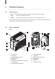
3 Product Overview 3.1 Unit versions The Defensor PH28/PH28A air purifier/air humidifier is available in two basic versions: – PH28: version with integrated water tank – PH28A: version with inlet valve for the connection to the drinking water system Both versions are equipped as standard with a coarse dust filter and a flock-coated evaporator mat to operate the unit as a humidifier (winter time operation). 3.
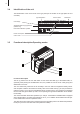
PH28A 8 1 10 9 18 16 17 2 12 3 14 13 7 6 4 15 5 1 2 3 4 5 6 7 8 9 3.
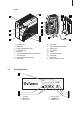
3.4 Identification of the unit The identification of the unit is found on the type plate (for the location of the type plate see unit overview): Type designation Serial number Month/Year Walter Meier (Climate International) Ltd. 8808 Pfäffikon Unit voltage Admissible water supply pressure (PH28A only) Type: PH28A Voltage: 220...240VAC / 50...60 Hz Water pressure: 0.5...6 bar Serial: XXXXXXX Power: max. 128 W Color code: NCS S 0300-N 07.
Two silver ionisation electrodes prevent the formation of slime and microorganisms in the base tub and on the humidification drum. The ionizer electrodes are active as soon as the Defensor PH28/ PH28A is switched on. Operating modes The Defensor PH28/PH28A can be operated in the following operating modes: – Operation as air humidifier In the humidifier mode the ventilator and the humidification drum are running only, if the actual humidity value is below the set reference value.
3.7 Accessories Defensor PH28 Defensor PH28A Filter set “Winter” (optimized for air humidification) Filter set for the operation of the unit during winter season. The set consist of: – Flock-coated evaporator mat – Coarse dust filter • • Filter set “Summer” (optimized for air purification) Filter set for the operation of the unit during summer season.
4 Commissioning 4.1 Unpacking the unit and checking the scope of delivery Unpacking the unit Open the packing and remove the unit and the accessories. Check the delivery for completeness (standard delivery, see chapter 3.8). Please contact your Defensor supplier in case something is lacking, they will be glad to send you the missing part without delay. Please check the equipment for damage. Please report any damage to your Defensor supplier and to the carriers, as required.
Choose location Please observe the following notes for the correct positioning of the Defensor PH28/PH28A: min. 150 mm 4.3 00 .1 in m m m 50 n. 1 mm mi 00 .4 in m m m – Place the unit on a solid horizontal surface, if possible free-standing and freely accessible (observe minimal distances). – A mains socket should be located close to the unit. – To ensure the entire volume of air is fully recirculated, do not place the unit in recessed compartments, closed corridors, behind curtains, etc.
– Install the air outlet grills in a way that the moist air can leave the unit unhampered and make sure the air flow is not directed towards obstacles (pillars, furniture, etc.) or cold outer walls (risk of condensation). 4.4 Connecting the water supply (PH28A only) The water supply has to be connected to the unit by a qualified specialist according to the illustration below. The installation data has to be maintained. The installation of a shut-off valve next to the PH28A is mandatory.
4.5 Putting the unit into operation Proceed as follows to put the Defensor PH28/PH28A into operation: • PH28: fill the water tank (see chapter 5.1) PH28A: open the shut-off valve in the water supply line. • Connect unit to the mains. CAUTION! Make sure the required supply voltage (see type plate) matches the local mains voltage, otherwise do not connect the Defensor PH28/PH28A to the mains! CAUTION! The Defensor PH28/PH28A must be connected only to grounded mains.
5 Operation 5.1 Filling the water tank (PH28 only) 1 Switch off the Defensor PH28 and disconnect the unit from the mains (pull the mains plug out of the socket). 4 Lay down the water tank carriage, remove the tank cap and fill the tank with tap water using the supplied filling hose. Do not use additives. Relocate the tank cap. Important! Screw on tank cap until it comes to a stop! CAUTION! In order to avoid water damage, completely remove any spilled water on the water tank carriage.
5.2 Switching the unit on and off Switching the unit on • Press the key. The unit loads the settings that were active when the device was shut down last. Upon completion the operating display appears. The look of the operating display depends whether the Defensor PH28/PH28A is operated in “Normal operating mode” or in “Program mode”.
5.3 Menu overview The following diagram shows the menu overview of the Defensor PH28/PH28A. After switching on, the unit is in the user level. User level In the user level you can define the settings for the normal operating mode (see chapter 5.4). BA3 Timer level In the timer level you can define and activate the program mode (see chapter 5.5).
5.4 Unit settings (normal operating mode) 5.4.1 Setting the desired humidity value Standard operating display modify Set value Set value 45%rH Set value confirm 45%rH New Value (see chapter 5.4.2) Set value cancel 30...90 %rH Old Value Note: The reference humidity value can be modified only if program mode is deactivated (see chapter 5.5). Setting range: 30...90 %rH Factory setting: 45 %rH Notes on setting: The optimum reference value depends on various factors.
5.4.2 Setting the fan step (see chapter 5.4.1) modify Fan power Fan power Auto1 Auto1 confirm Fan power New Value cancel Fan power (see chapter 5.4.3) Old Value 1...4 or Auto1...Auto4 Note: The fan step can be modified only if program mode is deactivated (see chapter 5.5). Available settings: 1, 2, 3, 4 or Auto1, Auto2, Auto3, Auto4 Operating mode Fan step “B” (Humidification) Behaviour Auto 1 runs fixed with fan step 1 Auto 2 automatic switching between fan steps 1..
5.4.3 Selecting the operating mode (see chapter 5.4.2) modify Operating mode Humidify Operating mode Operating mode confirm Humidify New Value (see chapter 5.4.4) Operating mode cancel Old Value Humidify, Purify, Combi mode Note: The operating mode can be modified only if program mode is deactivated (see chapter 5.5). 5.4.
5.4.5 Calling timer level (see chapter 5.4.4) Calling timer level Timer Timer Adjust On Leaving timer level (see chapter 5.4.6) For detailed information regarding the settings in the timer level see chapter 5.5 “program operation”.
5.5 Program operation The operation of the Defensor PH28/PH28A can be controlled via customisable operating programs. These programs allow to operate the unit at a preset time with the requested operating mode and fan step. This greatly facilitates the adaption of the Defensor PH28/PH28A to your particular requirements (e.g. adjusted to the business hours and/or working time).
5.5.2 Activating/Deactivating the program mode (see chapter 5.5.4) modify Timer Timer On Timer confirm On New Value (see chapter 5.5.3) 5.4.3 Timer cancel On/Off Old Value Available settings: On (program mode activated) or Off (program mode deactivated) Factory setting: Off Notes on setting: If program mode is activated the Defensor PH28/PH28A operates time-controlled with the operating programs (see chapter 4.3.4).
5.5.4 Setting the starting points and the operating programs (see chapter 5.5.3) modify Monday 1 --.-- 45%rH BA0 Monday 1 Monday 1 confirm New Value Monday 2 --.-- 45%rH BA0 Monday 1 cancel --.-- 45%rH H0 see notes on setting Old Value Sunday 2 --.-- 45%rH BA0 (see chapter 5.5.2) First select the desired day of the week or the starting point, respectively (Monday 1, Monday 2 ..... Sunday 1, Sunday 2), then define the operation settings which should become active at the starting point.
5.6 Locking/unlocking the keyboard The keyboard of the Defensor PH28/PH28A can be locked to prevent unauthorized access to the stored settings. Key lock Set • To lock the keyboard, press key until (approx. 4 seconds) the adjacent message appears in the display. The keyboard is locked now. Each time you press any key the adjacent message appears again. • To unlock the keyboard, press key until (approx. 4 seconds) the message “Key lock” disappears and the operating display is shown.
6 Maintenance 6.1 Maintenance intervals The Defensor PH28/PH28A can only provide full humidification and purification performance if the unit is regularly cleaned and the wearing parts are replaced. The maintenance intervals mostly depend on the load of the ambient air, the water quality and the operating time. Please consider the intervals for cleaning and replacing the individual components in the table below as approximate values.
6.2 Maintenance work 6.2.1 Disassembling the unit 1 Switch off the Defensor PH28 and disconnect the unit from the mains (pull the mains plug out of the socket). Defensor PH28A only: close the shut-off valve in the water supply line. 4 2 3 Press the snap and fold out the water tank cart. 5 Pull out the handle and slide the cart out of the unit. CAUTION! In order to avoid water damage, immediatelly remove any spilled water on the floor and on the components of the unit. 6 2. 1.
6.2.2 Cleaning work Unit component What to clean and how to clean Base tub, Retaining net, Rotary humidification drum • Wash parts with a lukewarm soap solution and rinse well with tap water. • Occasionally remove scale coating with a household decalcify agent (observe safety notes in chapter 6.3). Finally rinse the parts well with tap water. • Flush water tank with a lukewarm soap solution and rinse well with tap water.
Unit component What to clean and how to clean Coarse dust filters (Quattro filters) • Clean the coarse dust filters (Quattro filters) on the inner side with a vacuum cleaner (lowest power step). Note: As soon as the filter replacing message appears in the display (see error messages in chapter 7) replace coarse dust filters (Quattro filters) together with the evaporator mat evaporator mat. CAUTION! Make sure the filters do not get wet. Wet filters must be dry before reinstalling.
6.3 Notes on cleaning agent Only use cleaning agents stated in the table above. The use of disinfectants is only permitted if they do not leave any toxic residues. In any case the parts must be thoroughly rinsed with water after cleaning. DANGER! Household decalcify agent attacks the mucous membranes and the skin. Protect the hands, eyes and respiratory tracts therefore from contact with the agent and its vapour (wear gloves, goggles and work in a well ventilated room or outside).
6.4 Reassembly of the unit CAUTION! Before reassembling the Defensor PH28 check all components for possible damage. Do not reuse damaged parts but replace them before reassembling the unit Reassemble the unit as follows: 1 2 Install the vaporizer mat and the retaining mesh in the humidification drum. 4 Slide the humidification drum (with the internal geared wheel facing backwards) together with the base tub into the unit.
6.5 Resetting the filter changing message After the replacement of the filters and the evaporator mat the filter changing message can be reset as follows: 1. Switch on the unit (the filter changing message appears). Warning 6 Filter change Filter change ESC OK 2. Press the and keys simultaneously until the opposite message appears. 3. Press the key to reset the filter changing message and the interval counter. The standard operating display appears.
The operating voltage is specified on the type plate located inside the unit. DANGER! Never use fuses that do not match the above specifications and do not bypass blown fuses as this could rise danger to persons or material assets 6. Reinstall the fuse holder, the press the holder down until it properly engages. 7. Mount the terminal cover and tighten both mounting screws. 8. Insert and lock the water tank carriage (see chapter 5.1). 9. Reconnect the unit to the mains.
7 Fault elimination 7.1 Event messages Display Description Radio sensor K1 Cause: Install.? ESC/E Action: Radio sensor K1 Cause: Test Action: 7.2 If a new battery is inserted into the radio humidity sensor (option) and the radio channel of the radio humidity sensor does not correspond to the active channel of the Defensor PH28/ PH28A a beep sounds briefly (if the buzzer is activated) and a new radio channel (e.g. K1) will be proposed.
7.3 Error messages Display Error 1 red LED Buzzer Error relay Resetting flashes ––– activated Automatic resetting as soon as the water tank carriage (PH28) or the side cover (PH28A) is inserted correctly and locked. Cover open Error message is displayed until the water tank carriage (PH28) or the side cover (PH28A) is inserted correctly and locked. Cause: Water tank carriage (PH28) or side cover (PH28A) not inserted and locked.
7.4 What, if...? The following table lists symptoms of malfunction that may occur in daily operation of the Defensor PH28/PH28A, together with possible causes and suggested remedies. Symptom Cause Remedy Unit does not work, LC display Unit is not connected to the mains. Connect unit to the mains. remains dark Unit fuse blown. Have a service technician of your Defensor supplier check the unit. Unit does not humidify. Humidifier drum does not turn. Humidifier drum not correctly installed.
7.5 Notes on fault elimination DANGER! For the elimination of faults set the Defensor PH28/PH28A out of operation, separate the unit from the mains and secure it against inadvertent power-up. The elimination of faults must be carried out only by qualified and well trained professionals. Malfunctions relating to the electrical installation must only be repaired by authorized personnel or by your Defensor representative’s service technician.
8 Taking out of service/Disposal 8.1 Taking out of service If the Defensor PH28/PH28A must be replaced or if the unit is not needed any more, proceed as follows: 1. Switch off the unit, separate it from the mains and secure it against inadvertent power-up. Close shut-off valve in the water supply line (PH28A only). 2. Have the unit (and all other system components, if necessary) unmounted by a qualified service technician. 8.
9 Unit specifications Dimensions (B x H x T) 800 x 750 x 440 mm Weight (empty) 43 kg Operating weight 73 kg Water tank capacity 30 l Mains voltage 220…240VAC/50…60Hz oder 90…110VAC/50…60Hz Power consumption max. 128 W Capacity levels 1) 1 2 3 4 Air circulation rate 320 m3/h 420 m3/h 600 m3/h 750 m3/h Humidification capacity (at 25 °C and 20 %rh) 1.7 l/h 2.1 l/h 2.4 l/h 2.7 l/h Humidification capacity (at 23 °C and 45 %rh) 0.9 l/h 1.2 l/h 1.4 l/h 1.
10 Appendix 10.1 Wiring diagram PH28 Display Keypad&LED U1 S5 7 1 X9 1 10 1 X23 S4 1 2 3 4 5 6 7 8 9 10 Steuerprint PH27 300000642.000 Index XX Art.Nr. XXXXXXX X14 T2 P1 X15 X16 X9 +5V 4 3 2 1 X22 S3 1 2 3 4 5 X21 T1 1 U3 1.25 AT F1 +24V +24V X17 +24V U2 2 1 5 4 3 2 1 2 1 1 2 X10 X13 X12 X6 L1 L N PE X4 X3 St. 1 (ws) St. 2 (rt) St. 3 (gu) St.
10.
Pos. Art.-No. Spare parts designation 1 2560541 2561710 2 3 4 5 6 7 8 9 10 11 12 1109392 2560927 2560916 2533163 1103725 1115515 2560896 1103722 1103719 1103936 1106228 1109907 1103286 1110666 1102217 1100034 1110153 1116469 1103714 2560893 1103737 1114709 2561711 Outlet grill Outlet grill special color (RAL or NCS code according type plate) Fan cpl. Keyboard foil Synchronous motor cpl. Tothed belt pulley for motor Toothed belt Display LCD Control PCB Transformer cpl. Humidity sensor cpl.
© Walter Meier (Climate International) Ltd.
Consulting, Sales and Service: Solutions for Indoor Climate Reg.No. 40002-2 Manufacturer: Walter Meier (Climate International) Ltd. Talstr. 35-37, P.O. Box, CH-8808 Pfäffikon (Switzerland) Phone +41 55 416 61 11, Fax +41 55 416 62 62 www.waltermeier.com, international.climate@waltermeier.