Installation and Operating Instructions For the versions: yy BASIC yy STANDARD yy PROFESSIONAL Pool Safety System EN
1 Explanation of Symbols and Safety Notes 1.1 Explanation of symbols ........................................................................... 5 1.2 Safety notes ............................................................................................ 5 2 Overview 2.1 Notes on the installation and operating instructions ............................... 6 2.2 Operating principle "Active mode" . ........................................................ 8 2.
7 Using the System 7.1 Using active mode .................................................................................. 28 7.2 Preparations . .......................................................................................... 28 7.3 Alarm (active mode) ................................................................................ 28 7.4 After use . ............................................................................................... 29 7.5 ..........................
13 Troubleshooting 14 Technical Specifications 14.1 General . ................................................................................................. 43 14.2 Operational, transport and storage conditions . ....................................... 43 14.3 Power failure . ........................................................................................ 44 14.4 Monitoring bracelet battery capacity .......................................................
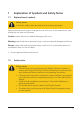
1 Explanation of Symbols and Safety Notes 1.1 Explanation of symbols Safety notes In the text, safety notes are marked with a warning triangle. Signal words denote the level of danger that would occur if the measures for minimising the risk were not followed. Caution means that minor material damage could occur. Warning means that minor personal injury or serious material damage could occur. Danger means that serious personal injury could occur.
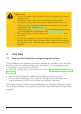
Safety notes yy Observe the safety notes contained in these installation and operating instructions. yy Risk of drowning! Initiate rescue immediately alarm sounds. yy The BlueFox system does not provide complete protection from drowning. Monitoring the swimming pool remains your personal responsibility. See Disclaimer, P. 44. yy The BlueFox system may only be used for the intended purpose and in the intended field of application. See Intended use, P. 10.
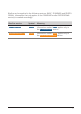
BlueFox can be supplied in the following versions: BASIC, STANDARD and PROFESSIONAL. Information that only applies to the STANDARD and/or PROFESSIONAL version(s) is marked accordingly. BlueFox version Symbol Meaning STANDARD STD Information marked STD applies only to the STANDARD version. PROFESSIONAL PRO Information marked PRO applies only to the PROFESSIONAL version.
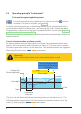
2.2 Operating principle "Active mode" Pool monitoring during bathing hours For pool monitoring during bathing hours the active mode must be activated. (For how to activate, see page 19). For each swimming pool user, a monitoring bracelet is pre-programmed with a personal alarm depth and alarm time – according to the user’s swimming ability. Programming is carried out using the PC program BlueFox Control (see Programming the alarm depth and time, P. 33).
If no button is pressed, all alarms will be cancelled 10 seconds after the monitoring bracelet is taken out of the water. All alarms are cancelled 6 minutes at the latest after the alarm was activated.
2.3 Operating principle "passive mode" Pool monitoring outside normal bathing hours For monitoring the pool outside normal bathing hours the “passive mode” must be activated. (For how to activate, see page 21). If the pool sensor registers activity in the pool (e.g. a person or object falling into the water) the following alarms are triggered. Warning lights and sirens, STD PRO radio alarm. The passive mode LED next to the padlock symbol flashes.
2.5 Package contents 1 Installation components 1 Bracket 2 Screws 2 Plugs 2 4 Alarm box with siren 1 Warning lights 2 12 V Connection 3 Pool sensor connection 4 Spare connection for 2 pool sensors PRO 3 3 m/10 ft PRO STD 1 Radio alarm dongle Plug-in mains adapter 10 m/33 ft 9 SENSOR Fig. 1 SENS OR R NSO SE Pool sensor PRO 2 Pool sensor 9 1 Pool sensor with cable Mounting ring 3 Screws Alarm box pool sensor Adhesive (solvent-free) Allan wrench 3 mm Fig.
USB plug-in mains adapter USB cable 1 Magnetic adapter (connects monitoring bracelet / USB cable) 2 Monitoring bracelet (1 pcs.) 1 Red and green LEDs 2 Water contacts (gold-plated) PRO Test unit Fig. 3 Monitoring bracelet accessories For further BlueFox system components, see Optional Accessories, P. 46.
3 Using the System for the First Time yy Read the installation and operating instructions. yy Charge the monitoring bracelet battery, see Charging the monitoring bracelet’s battery, P. 31. yy Install the BlueFox Control software, see Installing the BlueFox Control software, P. 36. yy Configure the monitoring bracelet for system test (alarm depth 5 cm, alarm time 5 sec.), see Programming the alarm depth and time, P. 33. yy PRO The supplied test unit can be used for the test.
4 Installing the BlueFox System yy Dispose of packaging materials in an environmentally acceptable manner. yy Read the Installation and operating instructions. 4.1 Installing and connecting the alarm box Only an approved specialist may connect the electricity supply, connect the unit to the mains and commission the alarm box. 4.1.1 Selecting a location for installation im Min m 2,0 m u Wall outlet Floor –– –– –– –– Minimum 1.
4.1.2 Installing the alarm box yy Hold the bracket to the wall and mark the drilling positions. 4 Tab facing up 2 2x 1 3 Danger! Electric shock risk! Connect the drill to a residual current circuit breaker. yy Drill the holes for the plugs (drill diameter 6 mm) and insert the plugs 1. yy Fix the bracket to the wall 2 (tab facing up). yy First fit the alarm box into the bottom of the bracket 3 and then click it in-place at the top 4. 4.1.
Procedure yy Connect the 12 V cable to the alarm box and screw tight. yy Fix the 12 V cable. Danger! Electric shock risk! Do not use extension cables between the plug-in mains adapter and the mains socket. yy Insert the plug-in mains adapter into a mains socket (with earth terminal) located away from the wet area. Use a residual current circuit breaker. (See above, Requirements for the plug-in mains adapter, P. 15). The last selected operating mode is activated (see Operating principle "passive mode", P.
yy Ensure that the plug on the pool sensor cable is dry. yy Connect the pool sensor cable to the alarm box and screw tight 3. yy If the pool sensor cable is too short: use an extension cable (see Optional Accessories, P. 46). 3 Fig. 5 SENS OR NSOR SE SENSOR Connecting the pool sensor to the alarm box yy Check the position of the pool sensor, see Testing active mode, P. 30. yy If test fails: Check the position of the pool sensor and test again.
Caution! Incorrect fitting of the pool sensor will prevent proper monitoring of the swimming pool. The side of the pool sensor marked "Sensor" must face into the swimming pool (water). 6 SENS OR R NSO SE SENSOR "Sensor" Fig. 7 7 8 3x yy After a minimum of 24 hours yy Push the pool sensor into the mounting ring 7 (route the pool sensor cable through the slot in the mounting ring 6). yy Tighten the screws using only slight force 8.
5 Alarm box operation Active mode (bathing hours) Monitoring using only monitoring bracelets System settings Passive mode (outside bathing hours) Fig. 8 5.1 Optical data entry confirmation 7 4 8 1 9 5 6 C 0 Deletes the last figure entered 2 OK Confirm entry 3 Alarm box keypad Operating modes The system allows the following operating modes: yy Pool monitoring during bathing hours.
Procedure: Press the button. If PIN protected: Enter the 4-figure PIN and then press OK (see page 27). Following successful activation the LED alongside the illuminate permanently.
5.3 Activating the "Passive mode" Pool monitoring outside bathing hours For pool monitoring outside bathing hours the “Passive mode” vated. must be acti- Note: A detailed description of the passive mode can be found on page 10. See page page 29 for a description of how the passive mode is used in day-to-day operations. Procedure: Press the button. If PIN protected: Enter the 4-figure PIN and then press OK (see page 27). The LED alongside the button will flash until the waves have subsided.
6 System settings Warning! When the “System settings” operating mode is activated, the BlueFox system does not monitor the pool and cannot trigger an alarm. Only activate the “System settings” operating mode when the pool is being monitored by another person. Proceed as follows to carry out system tests or to change system settings: 1. Activate system settings Press the button. If PIN protected: Enter the 4-figure PIN and then press OK (see page 27).
System tests Procedure / notes Enter "0001" and press OK. PRO STD Sending a test alarm to the radio module Testing the warning light Testing the siren The alarm box sends a test alarm to the radio module. The test alarm can be cancelled by pressing any button on the alarm box. Enter "0002" and press OK. The warning light flashes for 5 seconds or until any button on the alarm box is pressed.
System settings Procedure / notes Cancelling the siren Warning! Risk of drowning because the acoustic alarm is inoperable. Only deactivate the siren when the pool is being monitored by another person. Enter "1001" and press OK. When the siren is deactivated it will not sound if there is an alarm! Activating the siren Enter "1002" and press OK. The siren sounds if there is an alarm.
System settings Procedure / notes Changing the PIN Enter "2001" and press OK. Warning! Risk of drowning due to unintended deactivation of the pool monitoring system. If “0000” is selected as the PIN the following operating modes can be activated without entering a PIN: • Active mode (bathing hours) • Passive mode (outside bathing hours) • System settings Avoid unintended changes of operating mode by setting a PIN. Enter your new 4-figure PIN and confirm your entry with OK.
System settings Procedure / notes Resetting the alarm box to the factory defaults All of the BlueFox system settings will be reset to their factory defaults. Factory defaults PIN 0000 (change of operating mode possible without a PIN) Sensitivity of the pool sensors 2 (medium sensitivity) Time delay for automatically changing to passive mode 0 (does not automatically change to passive mode) Siren activated (the siren sounds in the case of an alarm) Enter "2002" and press OK.
6.2 Entering the PIN A PIN (Personal Identification Number) can be set to prevent operating modes from unintentional change. See Changing the PIN, page 25. or Select the desired operating mode by pressing the corresponding button. If a PIN has been set to prevent operating modes from being unintentionally changed, the LED to the left of the depressed button will start to flash and the 4 yellow LEDs above the keypad will prompt you (by flashing) to enter the 4-figure PIN. Enter the 4-figure PIN.
7 Using the System This section describes the optimum use of the system in day-to-day operations. Activate the “Active mode”or “Passive mode”. See 7.1 Using active mode, page 28 and 5.3 Activating the "Passive mode", page 21 7.1 Using active mode (with monitoring bracelet) 7.2 yy yy yy yy yy 7.3 Preparations Ensure that the system is connected to the power supply. Activate active mode see page 19. Test the system (see Testing active mode, P. 30).
7.4 After use yy Dry the monitoring bracelet using a cloth. yy Charge the battery if the red LED on the monitoring bracelet flashes at one-second intervals (when the unit is out of the water). See Charging the monitoring bracelet’s battery, P. 31. yy When the pool has closed: Activate passive mode (see page 21 yy Leave the system connected to the power supply. 7.5 Using passive mode 7.5.1 Preparations yy Ensure that the system is connected to the power supply. yy Activate passive mode (see page 29).
8 Testing active mode Caution! Risk of hearing damage caused by the sound pressure level from the siren! Wear hearing protection; keep children away from the siren. Immediately remove the test monitoring bracelet from the water once the alarm has activated. yy Configure the monitoring bracelet for system test, see Programming the alarm depth and time, P. 33. yy PRO The supplied test unit can be used for the test. yy Activating the "Active mode" (see page 19).
9 Monitoring bracelet Monitoring bracelet 1 Red LED 2 Green LED 3 Water contacts (gold-plated) 1 2 3 Rear 5 Connection for magnetic adapter (charging and communication with a PC) Serial number 5 Fig. 9 9.1 Monitoring bracelet Preparation yy Lightly shaking the monitoring bracelet will cause it to enter standby mode. yy When the green LED is flashing the monitoring bracelet is ready for use.
yy Charge the battery if the red LED on the monitoring bracelet flashes at onesecond intervals (when the unit is out of the water). Note: If the red LED on the monitoring bracelet begins to flash, the monitoring bracelet can still be used until the end of the day. Danger! Electric shock risk! Only use the USB plug-in mains adapter, USB cable and magnetic adapter in dry rooms. Caution! Humidity may damage USB plug-in mains adapter, USB cable and magnetic adapter.
9.3 Programming the alarm depth and time The alarm depth and alarm time are programmed using the BlueFox control software. Installation of the software is described in the section Installing the BlueFox Control software, P. 36. Caution! Humidity may damage USB plug-in mains adapter, USB cable and magnetic adapter. Only connect monitoring bracelets to the PC in dry rooms. Before connecting monitoring bracelets, dry them using a dry cloth.
5 1 3 4 2 Select the alarm depth and associated alarm time 1: Select a pre-set value 2 or use the slider 3 to enter the pre-defined alarm depth and alarm time. yy Click Save New Settings 4 to transfer the settings to the monitoring bracelet. yy Click Verify Settings 5 to read and verify the settings saved to the monitoring bracelet. yy Disconnect the monitoring bracelet from the magnetic adapter. yy Close the BlueFox control software: Close the window 34 .
9.4 Calling the status / Clearing the alarm / Resetting 6 7 8 yy Click Call Status to retrieve the battery and alarm status 6. yy Clear Alarm 7. yy Click Reset 8, if the monitoring bracelet is not recognised or if an error message appears after the monitoring bracelet is connected. Following a reset, the alarm depth and associated alarm time must be re-entered, see Programming the alarm depth and time, P. 33.
10 BlueFox Control Software 10.1 Hardware requirements For the installation and problem-free use of the BlueFox control software a Windows compatible PC with the following specifications is required: CPU at least 1 GHz (1.5 GHz recommended) RAM: min. 512 MB Display: at least XGA (1024x768) Hard disk: at least 50 MB free capacity USB interface 10.
yy Click BlueFox. yy Click Save, select the destination folder, then Save. The download will start. yy Open folder. yy Double-click on the Zip file. yy Double-click on the Exe file. yy Check the destination folder and if desired, change the destination by clicking Browse. yy Click Install. Installation starts.
Installation of the BlueFox control software is interrupted. The BlueFox control software requires the Microsoft .NET Framework 3.5 program. yy Click Yes to download and install the Microsoft .NET Framework 3.5 program. This process can take several minutes yy Accept the software license. yy Click Install. The process starts. The Microsoft .NET Framework 3.5 program has been installed. Installation of the BlueFox control Software is automatically continued and completed. yy Click Close.
10.4 Using the BlueFox control software See Programming the alarm depth and time, P. 33 and Calling the status / Clearing the alarm / Resetting, P. 35. 10.5 Uninstalling the BlueFox control software Path to the deinstallation program: Window Start menu > Programs > BlueFox_XX > BlueFox_XX_uninstall 10.6 Updates See www.bluefox-poolsafety.com Before installing an update the old version must first be uninstalled, see Uninstalling the BlueFox control software, P. 39.
11 Meaning of the monitoring bracelet LED displays 11.1 The monitoring bracelet in use Red LED Green LED Red flashes 1x /sec.: Low battery. yy Charge the battery Green flashes every 5 sec.: Monitoring bracelet is ready for use (in the water the LED double-flashes). Red flashes 5-times: Alarm sent. yy See Alarm (active mode), P. 28 yy See Resetting the monitoring bracelet, P. 28 Further LED flash codes are described in the section Troubleshooting, P. 41. 11.
12 Maintenance / Service yy Dry the monitoring bracelet with a cloth after use. yy Charge the battery if the red LED on the monitoring bracelet flashes at one-second intervals (when the unit is out of the water). See Charging the monitoring bracelet’s battery, P. 31. yy Occasionally clean the water contacts on the monitoring bracelet using methylated spirits. yy Protect the water contacts from soiling (e.g. sun cream). yy Clean the alarm box and cable with a damp cloth.
Problem Possible cause Solution During operation the alarm box transmits a short tone sequence. Power failure Have the mains connection checked by an approved electrician. See Safety notes, P. 6. The PC does not detect the monitoring bracelet, or an error message appears on the PC. No connection Check the connections (PC / USB cable / magnetic adapter / monitoring bracelet). Reset the monitoring bracelet, see Calling the status / Clearing the alarm / Resetting, P. 35.
14 Technical Specifications 14.1 General Maximum number of monitoring bracelets: unlimited Alarm box AC 100-240 V, 50 Hz Power consumption in standby: 0.2 W Power consumption in operation: approx. 1.3 W Siren: Sound power level approx. 100 dB(A) IP65 Monitoring bracelet Ultrasonic transmitter Rechargeable battery (see Charging the monitoring bracelet’s battery, P. 31) 14.2 Operational, transport and storage conditions Operating conditions Transport and storage conditions 100% incl.
14.3 Power failure If the power should fail the alarm box will sound a sequence of warning tones. See also Safety notes, P. 6. The operating mode of the alarm box will not change if the power is disconnected. 14.4 Monitoring bracelet battery capacity Hours of operation / week Battery charge sufficient for approx. Notes 0 10 months** Monitoring bracelet is not moved 3* 6 months** 14* 4.5 months** Assumption: The monitoring bracelet is not moved between use.
16 Warranty Deep Blue AG provides a product warranty in accordance with the laws of your country, but for a period of at least two years commencing with the date of sale of the BlueFox safety system to the end customer. The warranty applies solely to deficiencies attributable to material or manufacturing faults. When asserting warranty claims the original sales slip showing the date of sale must be attached.
17 Disposal Protect the environment! Packaging and old equipment contain recoverable materials that should be recycled. The BlueFox system or components thereof must not be disposed of along with normal domestic waste! Take old equipment to a collection point (EU Directive 2002/96/EC).
19 Name Configuration table Colour monitoring bracelet Alarm depth Alarm time (seconds) 47
Deep Blue AG Engenbühl 130 CH-5705 Hallwil Switzerland 24.01.2013 AP V1.0 Tel: +41 (0) 62 767 77 99 www.bluefox-poolsafety.com info@deepblue.