
User manual


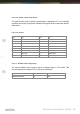


Table Of Contents
- Introduction
- Hardware description
- Software
- Appendix
- manual_e_delib.pdf
- Introduction
- Hardware description
- Software
- Appendix
- manual_e_ro_io_stepper2.pdf
- Introduction
- Hardware description
- Software
- DELIB API reference
- Management functions
- Error handling
- Stepper motor functions
- DapiStepperCommands
- DAPI_STEPPER_CMD_GO_POSITION
- DAPI_STEPPER_CMD_GO_POSITION_RELATIVE
- DAPI_STEPPER_CMD_SET_POSITION
- DAPI_STEPPER_CMD_SET_FREQUENCY
- DAPI_STEPPER_CMD_GET_FREQUENCY
- DAPI_STEPPER_CMD_SET_FREQUENCY_DIRECTLY
- DAPI_STEPPER_CMD_STOP
- DAPI_STEPPER_CMD_FULLSTOP
- DAPI_STEPPER_CMD_DISABLE
- DAPI_STEPPER_CMD_SET_MOTORCHARACTERISTIC
- DAPI_STEPPER_CMD_GET_MOTORCHARACTERISTIC
- DAPI_STEPPER_CMD_MOTORCHARACTERISTIC_EEPROM_SAVE
- DAPI_STEPPER_CMD_MOTORCHARACTERISTIC_EEPROM_LOAD
- DAPI_STEPPER_CMD_MOTORCHARACTERISTIC_LOAD_DEFAULT
- DAPI_STEPPER_CMD_GO_REFSWITCH
- DAPI_STEPPER_CMD_GET_CPU_TEMP
- DAPI_STEPPER_CMD_GET_MOTOR_SUPPLY_VOLTAGE
- DapiStepperGetStatus
- DapiStepperCommandEx
- DapiStepperCommands
- Example program
- Appendix
- manual_e_ro_serie.pdf
- Introduction
- Hardware description
- Ethernet Interface
- CAN Interface
- RS-232/RS-485 Interface
- USB Interface
- Digital in-/output modules
- Analog in-/output modules
- Stepper module
- Software
- DELIB API reference
- Management functions
- Error handling
- Reading Digital inputs
- Setting Digital outputs
- A/D converter functions
- D/A outputs management
- Stepper motor functions
- DapiStepperCommands
- DAPI_STEPPER_CMD_GO_POSITION
- DAPI_STEPPER_CMD_GO_POSITION_RELATIVE
- DAPI_STEPPER_CMD_SET_POSITION
- DAPI_STEPPER_CMD_SET_FREQUENCY
- DAPI_STEPPER_CMD_GET_FREQUENCY
- DAPI_STEPPER_CMD_SET_FREQUENCY_DIRECTLY
- DAPI_STEPPER_CMD_STOP
- DAPI_STEPPER_CMD_FULLSTOP
- DAPI_STEPPER_CMD_DISABLE
- DAPI_STEPPER_CMD_SET_MOTORCHARACTERISTIC
- DAPI_STEPPER_CMD_GET_MOTORCHARACTERISTIC
- DAPI_STEPPER_CMD_MOTORCHARACTERISTIC_EEPROM_SAVE
- DAPI_STEPPER_CMD_MOTORCHARACTERISTIC_EEPROM_LOAD
- DAPI_STEPPER_CMD_MOTORCHARACTERISTIC_LOAD_DEFAULT
- DAPI_STEPPER_CMD_GO_REFSWITCH
- DAPI_STEPPER_CMD_GET_CPU_TEMP
- DAPI_STEPPER_CMD_GET_MOTOR_SUPPLY_VOLTAGE
- DapiStepperGetStatus
- DapiStepperCommandEx
- DapiStepperCommands
- Output timeout management
- Test functions
- Example program
- Appendix

Hardware description |
Seite 57
2.5.1.1.3. 16-bit counter
The first 16 input channels have each a 16 bit counter. Thus, events as light
barriers, turnstiles or push-buttons are counted. Easy logical circuits are
realizable, which may e.g. switch one or several outputs, if a counter reached a
certain amount (set-point is reached). Please refer to the manual ”RO-series” to
implement such logical circuits into software.
2.5.1.1.4. Registering short input pulses
Short input pulses between to read-out cycles are registered through an
additional logic and can be separately read-out. A registered pulse on one or
more inputs is signalized by the LED ”Inputs: Change” on the control module.
The LED is extinguishing, if the software-register of the input state change is
read out by the user. For more indformation, see ”Register assignment”.
2.5.1.1.5. Galvanically decouppled through optocouplers
AC input optocouplers provide a galvanic isolation of the module towards the
connected equipment. They also provide a safe connection to the module for
reverse currents and high voltage peaks.