
User manual


Hardware description |
Seite 59
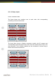
2.5.1.1.6.2. Visual control of the inputs
The state of each input is directly signalized by a separate LED. This simplifies
to detect and rectify wiring errors, because the signals on the cables are directly
observable.
2.5.1.1.6.3. Pinout
Port
Pin
Port
Pin
1
1a & 1b
9
9a & 9b
2
2a & 2b
10
10a & 10b
3
3a & 3b
11
11a & 11b
4
4a & 4b
12
12a & 12b
5
5a & 5b
13
13a & 13b
6
6a & 6b
14
14a & 14b
7
7a & 7b
15
15a & 15b
8
8a & 8b
16
16a & 16b
2.5.1.1.7. Variable input voltage range
The factory-default of the inputs is set to a voltage range of 15V to 30V. This
may be changed to a range of 5V to 15V (even afterward).
Input voltage range
5V – 15V
15V – 30V
Resistance value
1K
2K2