
User manual


Hardware description |
Seite 32
2.2.2. Configuring the module
In order to integrate a module into an existing bus system, it is necessary to first
assign a free module address and the appropriate bit rate. The ”special mode”
may be alternatively used to quickly operate the system.
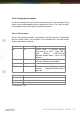
2.2.2.1. DIP-switches
Some of the settings are easily configurable using DIP-switches. Configurable
are the ”special mode”, the activation of the extended IDs, the data transfer
range or the module’s address.
DIP-switch A8
DIP-switch A7
Description
ON
ON
”special mode” -> Blinking squency
during start-up (5 LEDs, 1 right LED, 5
LEDs), 100KHz, CAN-ID=0x100,
Response-Module-Addr=1, keine 29 Bit
Adressen
ON
OFF
Only for SERVICE-purpose: application
won’t start. Forced into bootloader
OFF
ON
Software mode: configuration by software
OFF
OFF
DIP-switch mode: configuration by DIP-
Switches, Response-Module-Addr=1,
CAN 2.0A
DIP-switch
Description
A6 to A4
*) Setting up transfer rate
A3 to A1
*) Setting up CAN address
B8 to B1
*) Setting up CAN address
*) if A8 and A7 = OFF