
Setup guide

Dedicated Micros ©2006
37
DS2 Network Guide
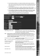
Function Description
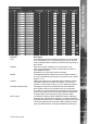
Input This identies which input is being congured. The unit supports
20 on-board alarms and 16 virtual alarms plus the unit can also
have an additional alarm modules connected each supporting 16
alarm inputs.
Enabled Each input must be enabled for it to be functional; if the
input is not enabled and an alarm is received the unit will not
acknowledge the alarm.
By default none of the alarm inputs are enabled.
Module This identies whether the alarm is from the onboard alarms or
one of the additional alarm modules. The options are Aux, Direct,
Module 1 to 16.
Contact Identify the contact that is associated with the selected module.
This option allows you to select from contact 1 to 20 for Aux,
Contact 1 for Direct and Contact 1 to 16 for additional modules.
Normally Closed Contact This applies to both the on-board alarms and the additional
alarm module, that can be connected to the unit via the 485-
bus. When an input is enabled then by default it will be normally
closed, removing the tick in the normally closed box makes the
corresponding input normally open going closed for alarm.
EOL Contact The End Of Line (EOL) option enables the inputs to detect any
changes in the input electronic resistance. A change outside the
expected values will result in a Tamper Alarm (short circuit or open
circuit) being detected as well as the system switching to alarm
mode. By default the EOL contacts are disabled for each input.