Digital Sprite 2 Network Guide
DS2 Network Guide Contents Network Configuration...........................................................3 Simple Configuration.............................................................5 Advanced Configuration......................................................21 Reviewing the Unit Logs......................................................92 Appendix A..........................................................................98 Appendix B – .ini Files..................................................
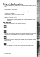
This manual is designed to help with the advanced configuration of the unit using the on-board web pages. To assist with the configuration of the unit, sections are constructed as tutorials and will illustrate how to perform common requirements. Use the tutorials that will provide the required functionality and follow the step by step instructions. In some of the sections the web interface and the OSD menus will be displayed.
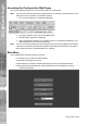
DS2 Network Guide Accessing the Configuration Web Pages The unit is configured using on the on-board web pages. To access these: Note: The unit should already have been configured with an IP address (via the serial port or the OSD menus) and connected to an Ethernet network. 1. Launch Internet Explorer (or Netscape Navigator). 2. Type the IP address of the unit into the address bar. 3. The Main Menu page will be displayed. 4. Note: Select Configuration Options.
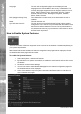
How to Configure Global Parameters There are some parameters that can be set that will affect the overall system; video standard for the video inputs, browser format for the web interface, language that the menus will be displayed in and the DST (daylight saving time) settings. To configure global parameters: 1. Select Home -> Main Set-up. DS2 Network Guide Simple Configuration 2. Note: Select the video standard from the drop down list; this will be the standard for all the video inputs on the unit.
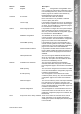
DS2 Network Guide Language DST (Daylight Saving Time) Reset Sync Unit time from PC The unit web configuration pages can be displayed in the language that is most suitable to the country of installation. The currently languages supported include; English, Spanish, French, Czech, Italian, Russian, Dutch, Portuguese, German, Turkish, Croatian, Danish, Finnish, Norwegian, Hungarian, Swedish, Polish, Arabic, Chinese This reflects the local time zone for the area where the unit is installed.
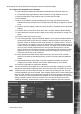
Cameras Alarms Network Tools Feature Register Description Note: Configuration and registration of the unit is carried out at the factory, therefore this screen is for fault diagnostics only and it is recommended that the page is not enabled unless advised by Dedicated Micros Technical Support. IP Cameras This feature will enable IP Cameras. Note: This feature is only available in software version 4.
DS2 Network Guide Live options Telemetry controls Live options Event controls Live options Playback controls This option allows the live pages to be tailored to the Operators requirements, disabling the option will remove all telemetry controls from the Live viewing pages. The unit supports an event database which can be accessed from the Live page, disabling this option will remove all event controls and will not allow the Operator to analyse the event database.
To configure the standard record settings: 10. Select the Edit Profiles button alongside the Standard Recording drop down box. 11. In the Profile Setup page select the JPEG resolution for High, Medium and Low. 12. Set the Image size for High, Medium and Low (these are set in KB). 13. Save Settings. 14. Return to the Camera and Record Setup page. From the drop down list select the Standard Recording resolution which corresponds to the settings configured in steps 9 to 12. 15.
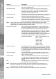
DS2 Network Guide Function Pictures/Second / milliseconds Description This allows the record settings to be configured as either Pictures Per Second or Milliseconds Standard Recording This is the resolution and image size of the images that will be recorded to hard disk for the cameras that are selected for standard recording and are edited in the profile setup page. The options are High, Medium or Low.
Description The unit can automatically detect if a camera source is present, the corresponding input will be enabled in this menu for connected cameras. Title It is possible to allocate an ASCII camera title to each of the cameras, which will be displayed onscreen along with the camera number. Terminated As the unit supports loop through it is necessary to remove the termination of any inputs that are ‘looped’, by default all inputs are terminated at 75 ohms.
DS2 Network Guide Note: Because the feed for this camera input will be delivered through the network, it is recommended that you select an input that does not have a camera connected at the back of the unit. 4. Change the Camera Type for the selected camera input to ‘IP’. 5. Repeat this operation for each of the IP feeds to be connected. 6. Click on Cameras->IP-Camera and Record Setup to configure each IP camera feed. 7.
As the unit can be connected to a LAN or WAN network it is possible to identify the maximum bit rate for the network connection. There are default settings for LAN, WAN and ISDN if these defaults are acceptable, select the corresponding button for your network link, the Max trans rate, transmit image buffers and Ethernet MTU values will be automatically configured, if these default settings are not as required, enter the new information in the sections. 6.
DS2 Network Guide DHCP Gateway DHCP Name Serial Number LAN, WAN, ISDN Force 10BaseT operation Transmit Image Buffers Ethernet MTU TCP Re-Transmit Timeout PPP Idle Line Timeout PPP Link Down Timer PPP Persistent Profile Packet Size Secondary Web Server Port If the unit is to be installed in a DHCP network, this option would display the gateway that was automatically allocated to the unit from the DHCP Server. This would be the name of the unit that is automatically allocated by the DHCP server.
Note: Priorities are not allocated to the PTZ control; this works on the initial connection and request having the control. Any subsequent connections will allow viewing but no control until the initial connection is relinquished or after a set period (5 seconds) where control commands have not been issued to the PTZ/dome camera. Any of the video inputs on the unit can be configured for coaxial telemetry; this is achieved in the Camera Set-up page. 1.
DS2 Network Guide Telemetry Setup Once the protocol has been selected it is possible to access the camera menus. This allows any functions supported by the camera to be configured. Telemetry Setup Page 1. Note: To access the set up parameters of the camera select the Telemetry Setup button on the Camera Set-up page. When you select the Telemetry Setup button, it may take a few seconds for the page and video to be downloaded, during this time do not press any buttons as this will slow the process down.
Select System -> Serial Ports & Telemetry. 3. Using the drop down list on the associated Communication port (Serial 3 (Bus A) or Serial 4 (Bus B)) select RS232/485 Telemetry. 4. Select the relevant telemetry type from the list of supported protocols. 5. Enter the dome/PTZ standard settings for: - Baud rate - Parity - Data bits - Stop bits - Flow control 6. Ensure the address of the dome/PTZ camera is the same as the video input number on the unit, e.g.
DS2 Network Guide Baud rate, parity, etc This allows the communication settings to be configured, note when telemetry is selected these will not be active and will default to predetermined settings.
The unit can be incorporated into an existing analogue matrix installation and offers control of the matrix via the Live web page or the Viewer software. This ensures that any existing equipment does not need to be removed from the installation to allow control over a network, simply integrate the unit into the system a network output. The unit supports connectivity to the matrix on any of the Serial Ports.
DS2 Network Guide Function Serial1 & Serial2 Description Serial ports 1 & 2 are RS-232 ports and can have the following port usage assigned; off, debug, general purpose, PPP and text in image, RS232 telemetry. Serial 3 & 4 (Bus A and Bus B) Serial ports 3 & 4 are RS-232, RS-422 and RS-485 ports and can have the following port usage assigned; off, debug, general purpose, text in image, RS232/485 telemetry. Telemetry type This is the list of serial telemetry protocols that are supported on the unit.
How to Configure Profile Recording The unit supports MultiMode recording. This offers the ability to set different recording rates, resolutions and compression formats across scheduled, normal and alarm modes for each individual camera. By varying the quality, bit rate and file size of the recorded images using the MultiMode function can increase recording capabilities of the unit. MultiMode offers: Ability to set different recording resolutions including 720x512, 704x256, 352x256 and 176x128.
DS2 Network Guide Using the Profile Wizard It is possible to set the unit recording configuration based on the users priorities. Using the Configuration wizard, the Administrator can set the unit configuration according to the users priorities. To use the Camera Profile Wizard: 3. Select Cameras -> Profile Wizard. 4. Input the number of days that images should be stored by the system before being overwritten. This will influence the quality and rate of images being stored. 5.
The unit is now ready for Profile Recording. Editing Camera Profiles DS2 Network Guide 9. Save options by selecting Save Settings button. The Camera Profile menu is an alternative to using the Profile Wizard for configuring Profile recording. This allows each camera to be individually configured for normal and alarm recording and pre alarm data. First it is necessary to configure the MPEG4 and JPEG profiles on the unit. All camera recording parameters for the unit are defined on this page.
DS2 Network Guide Function MPEG4 Profile Name MPEG4 Bitrates (Kb/sec) MPEG Quality MPEG4 Framerate (pps) MPEG4 sec between I-Frames Description This is a user defined description that identifies a particular set of parameters. This parameter designates the rate at which data will be transferred or recorded. This parameter defines whether the bandwidth allocation will be a set figure (Constant Bit Rate) or will fluctuate depending on the quality of the image being recorded.
Record Rate Resolution code Description This field can be edited to something significant for the Administrator. This field either displays the pictures per second recorded under this setting, or the milliseconds between each picture, depending on the selection at the top of the table. The drop down menu allows selection of a suitable resolution for this profile, from the settings at the top of the page (See JPEG Resolution Alias).
DS2 Network Guide Note: The Record Duration at the top of the menu gives an indication of the number of days and hours storage that can be achieved and includes Standard and Profile record settings. Function Camera Title Schedule Mode Normal Profile Alarm Profile Pre Alarm Pictures Pre Alarm Rate Description This identifies the camera title as allocated in the Camera and Record Setup menu. This displays the operating mode.
To record the audio associated with Camera 2, enable Audio in 2. 5. To record the Audio coming in from NetVu ObserVer, enable Remote Audio. 6. Enable Audio Output 1 to be able to send audio out of Output 1 (typically to a remote speaker). 7. Enable Audio Output 2 to be able to output the audio from the camera being viewed (either Camera 1 or Camera 2) along with any network audio (typically the control room audio). 8.
DS2 Network Guide This can then trigger a number of operations such as FTP alarm notification and increase camera recording rate for the corresponding video input. Note: It is recommended that you utilise the Walk test function to ensure the settings are correct for each input enabled, if the settings are too low this will mean VMD will not be identified to high and false alarms will occur.
If the VMD notification is to be disabled when the Operator is controlling the camera, enable the inhibit when moving option Inhibit when not at park This option will enable VMD on the camera when it returns to the park position, at all other preset positions VMD will be disabled Preset This identifies the preset position that will be the Park preset when using the inhibit when not at park option VMD pulse extension The pulse extension extends the trigger to avoid double triggers of VMD from occurring, i.e.
DS2 Network Guide Function Create Database Entry Change Standard Record Rate Change Profile Record Rate Report on VMD Activity Day Operation Night Operation Weekend Operation 24 Hour Alarm Record Still Image Protect VMD Images Create Zone Input 30 Description This will record an event in the database using the VMD Zone number (refer to Alarm Zone below for more information). This will set the alarm record rate across ALL cameras that are enabled in the record sequence.
Email Image Email Image Resolution This will mark the VMD event for automatic download to the FTP Server identified or to the Archive list. This will automatically e-mail a snapshot of the VMD incident to the SMTP server identified, refer to Email configuration page for more information. This is a system setting, the selected resolution will affect any option where snapshot images are possible, i.e. alarms, VMD, etc.
DS2 Network Guide 13. It is possible to have a grid overlay displayed on the image to assist in placing the zone areas, select graticule on to display the grid. 14. Select the next zone from the drop down box to create another zone area and follow Step 16. Note: 32 If this is incorrect then you can click again and the zone will move to the new area.
16. Select the zone mode from the drop down box that will apply to the zone you have selected see below for description of zone modes. DS2 Network Guide 15. If you want to use the default zone settings you can select the default grid option, this will place 16 zones over the image. You will be presented with a prompt, select Yes. 17. Set the pixel count (%) by selecting from the drop down box the range is between 2 and 100%. 18.
Function Camera Zone Mode Pixel Count (%) Pixel Change (%) Sensitivity VMD / Activity Clear Cells Default Grid Description This is a drop down list of the video inputs on the unit, selecting one of the inputs will display the corresponding video source. This is active when either Activity or VMD is selected. There are 16 advanced VMD zones that can be individually configured, select the zone from the drop down list. This is active when VMD is selected.
Displays a grid to assist in identifying and creating zone areas. This is disabled when the Activity option is selected. This is active when VMD is selected. Zone Display Only This will display the areas of the image that are covered by a zone only and will assist you in ensuring the necessary areas are covered. Resolution This is the resolution of the reference VMD image being displayed. Refresh This will update the reference image to the latest view during set up.
DS2 Network Guide How to Enable and Configure Alarms The unit supports 20 alarm inputs which can be individually configured. This section will be divided into: Enabling and configuring the alarm inputs Enabling and configuring the alarm actions By default the 20 alarm inputs are disabled, these need to be enabled so that external alarm devices can be connected to the unit. 1. Select Alarms/VMD -> Alarm Inputs 2.
DS2 Network Guide Function Input Enabled Module Contact Normally Closed Contact EOL Contact Dedicated Micros ©2006 Description This identifies which input is being configured. The unit supports 20 on-board alarms and 16 virtual alarms plus the unit can also have an additional alarm modules connected each supporting 16 alarm inputs. Each input must be enabled for it to be functional; if the input is not enabled and an alarm is received the unit will not acknowledge the alarm.
DS2 Network Guide Nuisance Count Stuck Time Pulse extension This is a repetitive detector value. When an alarm is received on the unit it will store the alarm time and will monitor the number of times the same detector is triggered within an hour period. If the detector is triggered the number of times that has been set for the nuisance count then the unit will de-activate this detector from triggering an alarm on the system for an hour.
11. The zone AND input allows you to configure a situation where an alarm must be received on both the zone alarm input and the zone AND input to force the Digital Sprite 2 to go into alarm mode, select the appropriate option from the drop down list. 12.
DS2 Network Guide Note: There are a number of zones which have been pre-configured; Zone 27 Archive Slow, Zone 28 Archive Fault, Zone 29 Disk Low, Zone 30 Disk Full, Zone 31 Disk Fault, Zone 32 Panic alarm. Zone Title Pre-Alarm Time Alarm Duration Zone Alarm Input Zone OR Input Zone AND Input Zone NOT Input This information is stored along with the images in the database, ensure this has relevance to the alarm trigger. There is an option to use the camera title.
DS2 Network Guide Function Select Zone Cameras Alarm Zone Actions (select all) Zone on entry route Zone on exit route Entry Initiator Exit terminator Text Only Alarm Create Database Entry Dedicated Micros ©2006 Description This allows you to select one or more cameras that will be associated with the Alarm Zone being configured. Each camera will become part of the ‘alarm sequence’ when this alarm zone is triggered.
DS2 Network Guide Change Standard Record Rate Note: This will change the record rate of the cameras that have been identified in the Standard Record Rate page (refer to Camera Setup for information on how to configure standard record rate). The cameras will switch to the alarm record rate specified. Changing the zone cameras has no effect on which cameras have their standard record rate changed.
The unit supports the ability to automatically send a camera to a preset position on the receipt of an alarm. Within this web page it also possible to identify if the alarm is to be available as a trigger for an alarm zone. To enable and configure alarm presets: 1. Select Alarms/VMD -> Alarm Presets 2. Select the camera that will be sent to the preset position from the drop down list. 3. Enter the pulse extension in seconds. 4.
DS2 Network Guide Contact Number Normally Closed Contact Preset Zone Trigger The Auxiliary input and the additional alarm modules support sixteen input contacts any of these can be allocated as the alarm input trigger. The alarm trigger can be configured as normally open (default) or normally closed. The preset position is the position the camera will move to when the alarm is triggered. It is possible for a camera specific alarm to also trigger an alarm zone.
Global VMD Global Camera Fail Schedule Notification Primary Signalling Failure Weekend Notification It is possible to configure any of the onboard or additional module relays to be the default global alarm relay, this means that the relay will close when an alarm is received on any of the alarm inputs. It is possible to configure any of the onboard or additional module relays to be the default global VMD relay, this means that the relay will close when VMD is identified on any of the camera inputs.
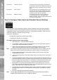
DS2 Network Guide Enabling PPP for dialling into the unit Enabling PPP and identifying specific modems for dial up Configuring Alarm/VMD Reporting via the web and editing the profile.ini file How to Enable and Configure PPP via Serial Port The PPP facility on this unit is designed to be used in two contexts; 1) As the only network connection on the system. 2) As a backup connection in the event that the primary connection is available when trying to dial out on alarm.
EVENT PrIP - 192.168.1.2 COPY GOTO 1 2 3 4 5 6 7 8 9 10 11 12 13 14 15 16 MODE LIVE PLAY SPOT ISDN TA PPP client address - 172.16.100.241 Phone No. - 09876 MENU RECORD ISDN Cat5 LAN Serial ISDN TA PPP server address - 172.16.100.250 PrIP - 172.16.100.253 Phone No. - 12345 Serial PC running EDP PrIP - 172.16.100.201 PrIP - Private IP address PuIP - Public IP address DS2 Network Guide DVR Cat5 LAN 1. Use FTP client software to connect to the unit.
DS2 Network Guide # # username username dm password password password PPP_Link2 1234567890 PPP_Link1 1234567890 Ether1 1234567890 10.0.0.1 10.0.0.1 10.0.0.1 255.255.255.0 255.255.255.0 255.255.255.0 # Note: Any lines marked with a # are comment lines and will be ignored by the system. To set up PPP to connect the unit to a PC, the PPP settings need to be edited: Username & Profile Label username dialout dm 4.
Set up the unit serial port to dial out DS2 Network Guide When you’ve entered those fields remember to select under what circumstances you want to the unit to dialout on (alarms, camera failures etc). The system now has the dialout profile used to control the connection, and the information on which number to call to. We now need to configure the serial port to use the TA (or modem). Note: 1. Plug the TA into COM port 2. 2. Click on System->Serial Ports & Telemetry 3.
DS2 Network Guide 1. Click on Start-> Control panel -> Network Connections 2. Select ‘Create a new Connection’. 3. On the pop up window that appears, click ‘NEXT’ 4. Select ‘SETUP AN ADVANCED CONNECTION’ and click ‘NEXT’ 5. Select ‘ACCEPT INCOMING CONNECTIONS’ and click ‘NEXT’ 6. Select the TA or modem you have installed on your PC and click ‘NEXT’ 7. Select ‘DO NOT ALLOW VIRTUAL PRIVATE CONNECTIONS’ and click ‘NEXT’ 8. On the User Permissions screen, click ‘ADD’ 9.
DS2 Network Guide 10. Click ‘OK’. You should now see the new user in the users list. Make sure it has a tick in the box next to it. Click ‘NEXT’. 11. You should now see the Networking Software screen, make sure Internet Protocol is highlighted and click ‘PROPERTIES’. 12. In the TCP/IP properties assign a network range for Windows™ to assign to the PPP client (Windows™ will give a PPP address to the unit). This should encompass the IP address set on the unit.
DS2 Network Guide 13. Click ‘OK’, then ‘NEXT’ and then ‘FINISH’ The PC should now be set up for alarm receiving. Using PPP as a backup to Network Alarms For the purpose of this tutorial, the Unit is connected between the network and a serial TA (or modem). The TA is connected to an ISDN line or PSTN Modem. The receiving PC is networked and has NetVu ObserVer running with the Event Distribution Point Software, and is also connected to and ISDN or PSTN Modem.
DS2 Network Guide Create a connection profile 1. Use FTP client software to connect to the unit. To connect to the unit type the IP address of the unit in the FTP software, you will be prompted for a user name and password; the default settings for these are dm and ftp respectively. 2. Locate the ‘profile’ file within the /etc folder. 3. Open the file with a text editor.
DS2 Network Guide # # # # # username username dm ------------------Profiles Table List ------------------ password password password PPP_Link2 PPP_Link1 Ether1 1234567890 1234567890 1234567890 10.0.0.1 10.0.0.1 10.0.0.1 255.255.255.0 255.255.255.0 255.255.255.0 # End of file Note: Any lines marked with a # are comment lines and will be ignored by the system.
DS2 Network Guide Note: Note: 1. Click on Alarms/VMD -> Alarm/VMD Reporting. 2. The primary connection uses the network port. 3. To set up the secondary connection, enter the IP address of the target PC running NetVu ObserVer and the EDP in the ‘Host’ column. 4. In the ‘Profile’ column, enter the profile name created in the last step. Use the correct username/profile label configured in the PROFILES file. This informs the system which settings to use. 1. Plug the TA into COM port 2. 2.
DS2 Network Guide Note: The ISDN TA could be replaced with a modem which then dials another modem connected to a PPP Server. The unit is now configured for ethernet dialout on primary, and ISDN on secondary. Set up the unit serial port to dial out The system now has the Dialout profile used to control the connection, and the information on which number to call to.
It is possible to identify the host information, as displayed on the web page, within the hosts file in the \etc directory. To configure the remote alarm station information using the web interface: 1. Select Alarms/VMD -> Alarm/VMD Reporting. 2. Enter the IP address of the primary remote host, this is required for connections via the network and via the serial ports. 3. When making a connection via the Ethernet network enter Ethernet to identify the medium by which the connection will be made.
DS2 Network Guide Function Primary Host Secondary Host Profile Note: Public (NAT) IP Address Video Server Port (port fwding) Unit Alarm Name Remote Alarm Reporting Remote Camfail Reporting Remote Tamper Reporting 58 Description This is the IP address or name of the initial host that the unit will transmit an alarm message to. If the unit is unable to contact the primary host then it is possible to identify an alternative route and a secondary host.
Dial Retry Time Dial Limit Alarm Telnet Server Port ARC Ping ARC Multi-Ping This will send an alarm report when the unit starts up, this will identify any system resets. If the initial connection attempt fails then the unit will wait for the specified time period before attempting to re-connect. If using Multi-Ping, this will be the period between 30 second ping transmissions.
DS2 Network Guide 8. It is possible to enable an FTP download and more regular intervals by enabling the polled option, once enabled identify the time period between the end of one FTP download to the start of the next. 9. If the FTP download is only to be initiated by the Operator then enable the manual download option. The FTP download will only commence when the Start Download button is selected. 10.
To access an FTP Server it is necessary to go through an authentication process, this is the username for you to gain access to the FTP Server. Password To access an FTP Server it is necessary to go through an authentication process, this is the password for you to gain access to the FTP Server. On Connection This will automatically start the Archive download when the unit detects the archive destination is present (CD/DVD or network).
DS2 Network Guide The typical process for SMS messaging is: The unit will send a message to the mobile phone. This can be on receipt of an alarm or manually initiated. The operator then has the option to send a message back to the unit or log onto the unit using the web interface or Viewer software. If the Operator is remote they can send a message back to the unit to action the Server to send an alarm message to a remote viewing application.
Enter the callback profile in 0 and 1, this is the route the text message from the Operator will take when sending a message back to the unit. 7. Enter the password to enable SMS commands to be initiated. This password will be included in the text message from the Operator. 8. Select the advanced setup button to enter details on the GSM module that will be used in the system. 9.
DS2 Network Guide Report startup This will enable the unit to transmit a message on power up of the unit. Report alarms Sends a text message on receipt of an alarm via the onboard or additional alarm inputs. Report camera fail If any of the enabled video inputs on the unit does not detect a 1 volt peak-to-peak signal then the unit will send a SMS message. Report VMD activation If VMD is identified on any of the enabled video inputs the unit will send a SMS message.
This can be a number or name that has been configured on the SMS Set-up page, this will be via the serial port or Ethernet connection. This is the text message that will be sent to the remote viewer informing the Operator of an incident and therefore should be meaningful. text How to Configure E-mail Settings The unit can automatically transmit and e-mail to an SMTP Server under numerous conditions, including on start up of the unit, on receipt of an alarm, or camera failure.
DS2 Network Guide Function Connection Profile Description It is possible for the e-mail to be transmitted via the Ethernet network or dial up connection. This setting presumes that a modem has been connected or configured and the unit is connected to a LAN or WAN and allocated a valid IP address. Mail Server This is the IP address or DNS name of the SMTP Server that the e-mail from the unit will be sent to. The SMTP server will then forward this onto the recipient.
To protect existing recorded images: 1. Select Alarms/VMD – Alarm Image Protect/Unprotect, If there are any existing protected images these will be displayed within the protect image partition summary. 2. Enter the start and end time and date and select Protect Images to display the corresponding recordings. 3. Highlight the recorded file in the protect image partition summary. 4.
DS2 Network Guide Function Start Date and time End Date and time Protect Image Partition Summary Unprotect Images Protect Images Protect Images Indefinitely Description This allows you to enter the start time and date for the period you wish to search for recorded images. This allows you to enter the end time and date for the period you wish to search for recorded images. The recorded files will be displayed within this area. These are then selected to either unprotect or protect.
Description This is a read only section and is generated by the unit, it identifies the last time that the database was reset. How to Configure an Alarm Schedule DS2 Network Guide Function Last database reset time It’s possible to utilise the onboard schedule function of the unit to enable and disable alarm triggers and VMD activation and to determine when specific record rates will be enabled. This can reduce unnecessary alarm triggers, e.g.
DS2 Network Guide DAYTime NIGHTTime This identifies the time when the unit will switch to Day operation mode. This identifies the time when the unit will switch to Night operation mode. 6. If Weekend operation is to be active, enable the option and configure the start and end times, weekend settings will be applied to the recorded video during this time period. 7. Select the schedule type from the drop down list. 8.
Function Current System information Current PC information Current system state Force mode buttons DS2 Network Guide When the override time entered elapses the unit will go back to the normal operating mode and the screen will reflect this. Description This information details the date, time, GMT offset and current time zone. This details the information on the PC that is being used to force the unit into one of the operation modes, this includes date, time and PC GMT offset.
DS2 Network Guide It is possible to integrate the unit into a system where text information can be stored with the relevant images for review at a later date, e.g. Retail, Finance. The unit can be configured to search for specific text information, allowing for fast retrieval and review of images. This section is divided into: Enable text in image on the serial port. Configuring the paths.ini file to specify the communication port and text information.
Enter the text information in the .
DS2 Network Guide Function Number of lines in Image Line length Image display overlay options Number of visible lines Description This is the number of lines that will be displayed in live and replay (via the web pages) along with the relevant images. The default setting is 10 lines. This identifies the length of the lines that will be stored with the image. The default setting is 80 characters which is generally the full screen.
All four serial ports on the BX2 support the option for Text In Image, it is also possible to use the Network port on the unit. For serial transmission ensure one of the serial ports is configured appropriately (System -> Serial Ports and Telemetry), then select the port from the drop down list.
DS2 Network Guide Keyword Triggers This ties in with the 32 keywords previously configured. Enable the keyword(s) that is be used as a trigger for the camera being configured. How to Configure the Onboard Firewall The unit supports an on-board Firewall to add to the security of the unit. The Firewall can be enabled and work in conjunction with the security applications that are already present in the network.
DS2 Network Guide Note: If you enable this function ensure the IP address of the PC you are using to configure the system is also in the list. If the address is not added then you will be unable to communicate with the unit via the network, it is important to take this feature into account when the unit is on a DHCP network, where IP addresses are allocated automatically. If no IP addresses are specified than any IP address can connect to the unit.
DS2 Network Guide Alternatively it is possible to identify the supported ports and also determine who is connected to the unit via a telnet session. At the prompt enter: TCP Ports The information displayed should look like this. IP Address Range and Subnet When entering a range of IP addresses in the Firewall it is necessary to calculate the relevant subnet that does not mask out the first IP address to the last IP address in the range.
255.255.255.192 255.255.255.224 255.255.255.240 255.255.255.248 255.255.255.252 255.255.255.254 0 - 63 0 – 31 0 – 15 0–7 0–3 0-1 How to Enable System Logs There are numerous actions that the unit can be configured to automatically carry out on receipt of; an alarm, VMD activation, Schedule function, etc. When these triggers are received and the actions initiated then it is possible to log this information within the unit System Logs. DS2 Network Guide 192.168.3.1/26 192.168.3.1/27 192.168.3.1/28 192.
DS2 Network Guide How to Configure Watermarking The unit supports the facility to watermark recorded images. It is also possible to produce a watermark certificate which proves that an image has not been altered or tampered with, using a unique MD5 signature which will change if the image files are changed. This process can assist with the audit trail process for digital recorded video.
DS2 Network Guide How to Configure the Webcam functionality Any of the video inputs on the unit can be made available to be transmitted to a webserver via FTP. These images can then be incorporated into a web page and accessed via a standard web browser. This function gives users the opportunity to incorporate video images into their Corporate web site.
DS2 Network Guide Note: 7. Enter the update interval in seconds, this identifies the time between updated files being transmitted from the unit to the FTP Server. The speed and cost of the network connection being used should be taken into account when setting this time period. 8. Enable the video input(s) that are to be made available for webcam functionality. Images from these inputs will be transmitted to the FTP Server for integration into web pages. 9.
Note: Enable batch transfer and images will be transmitted to the FTP Server in a ‘batch’, e.g. the unit will take ‘snap shots’ from video inputs 1, 2, 4 and send these in a single batch to the FTP Server. If this is disabled then the unit will transmit files individually. The delay between batch files being transmitted is the update interval, e.g. every 10 seconds the unit will send images from video inputs 1, 2, 3.
DS2 Network Guide Webcam Resolution Webcam Enabled This is the resolution of the images, defined in the Camera and Record Setup Page, that are transferred to the FTP Server. Take into account the speed and type of network connection being used when selecting the resolution. The webcam functionality can be enabled at specific times (DAY, NIGHT or WEEKEND mode). If the webcam functionality is to be disabled it is recommended that the option also be disabled in the Advanced Features option.
1. Select System -> User Accounts. Note the page may take several seconds to open as the data from the units is being downloaded for display. 2. Press the Add button within the Video Accounts Administration section. 3. Enter the new User Name, Password and which cameras on the system will be available to the user in Live and Playback mode. 4. Press Save, the user account will be updated and added to the list. This may take several seconds.
DS2 Network Guide 2. Modify the information as required. 3. Press Save, the unit will update the information. To delete an account: 86 1. Highlight the user account. 2. Press the Delete button. 3. You will be prompted to confirm the account is to be deleted.
DS2 Network Guide Function Description System Accounts Administration Within this section the system accounts that have been preconfigured using the .ini files will be displayed. This allows the username and password of these accounts to be easily modified. Note: Please ensure all configured Usernames and Passwords are retained as loss of this information may result in the unit being returned to Dedicated Micros.
DS2 Network Guide Function Comb Filter Enabled Local 4CIF Interlace Enabled Camera Title Colour Contrast Description The Comb Filter improves image clarity and is turned on by default. Some NTSC line locked cameras may give better image quality results with the Comb Filter disabled. This can be enabled if the system will be used to record using 4CIF settings, and will eliminate the comb effect that may be visible in a high motion recording environment.
DS2 Network Guide Function Comb Filter Video Input Resolution Input Path V and H Position Show Trace RGB Description This feature improves image clarity and is turned on by default. Some NTSC line locked cameras may give better image quality results with the Comb Filter disabled. This is a drop down list of the available video inputs on the unit. This is a drop down list allowing selection of the resolution being viewed/traced (high, medium and low).
DS2 Network Guide Relay Test Page The relay test page allows you to test the onboard relays and the additional relay modules. The unit supports six onboard relays and up to two additional relay modules, these modules have sixteen relay connections each. To test the relay select the tick box adjacent to the relay number, save the configuration. Press the OK button and this will trigger the corresponding relay.
This option has already been covered in the Configuration section of this manual; please refer to How to Enable and Configure Watermarking for details of this option. System Variable DS2 Network Guide Watermarking This page can be used for system diagnostics as it provides a readable overview of the configuration parameters of the unit. Any information that has been configured and stored on the unit will be shown on the file. Typical information is; camera titles, alarm title.
DS2 Network Guide Reviewing the Unit Logs The unit can be configured to produce a number of log files, these are for: PPP connections Anonymous FTP connections Illegal file access attempts FTP and telnet users System Logs Setup Configuration of these logs is detailed in the Configuration section of this manual. The logs that are generated can be viewed via the web interface on the unit. To access the logs: 1.
Log Telnet/FTP Any web access to a CGI protected directory or non-access existent file will be logged with an IP address, time and type of action This will log users that are trying to gain access to the users unit using an FTP or telnet session Connection Log This log details all FTP and telnet connections made to the unit. Telnet and FTP can be allocated a username and password by enabling and configuring the option within the USER.
DS2 Network Guide The Security Log identifies the users that have attempted to access the Configuration pages or any password protected page on the unit Web interface and have entered an incorrect password. The information logged is: The action requested and status Time and date IP address Port information This information can be used to monitor the connections to the unit and identify unauthorised actions. The following shows typical log information; Attempt to access to frmpages\index.
Content-Transfer-Encoding: 7bit Site-Id: DS2
System-Exception: Camera fail 3 at Wed Jun 30 14:21:26 2004 +0200
250 OK QUIT 221 closing connection Sent Message Log DS2 Network Guide Content-Type: text/html; charset=us-ascii; This logs all the SMS message information. There are various options that can be configured to allow an SMS message to be sent; start up, alarms, etc.
DS2 Network Guide This ensures current and recent information is always available. The information detailed is; Time and date, Reset Code and Reason, Connection-status, Site and ARC ID.
Sat Apr 24 05:53:50 2004 (+0100): FTP FAILED LOGIN User: [test] Password: [test] Sat Apr 24 05:53:50 2004 (+0100): Foreign IP 62.214.19.65 Sat Apr 24 05:53:50 2004 (+0100): Socket no 82, myport 21, hisport 4953 Sat Apr 24 05:53:50 2004 (+0100): FTP FAILED LOGIN User: [test] Password: [test12] Sat Apr 24 05:53:50 2004 (+0100): Foreign IP 62.214.19.
DS2 Network Guide Appendix A Reset using Telnet An alternative option for resetting the unit is to connect to the unit using telnet. 1. Go to Start -> Run. 2. Enter > 3. You will be prompted for a username and password (default dm and telnet) and press return. Echo is enabled on the unit for telnet. 4. Type , the unit will reset itself and will not be available for a few minutes.
Editing the ini Files using FTP Client Application There are a number of parameters that can be configured within the ini files on the unit. This section details the files, their function and how these are configured.
DS2 Network Guide 100 5. Click OK. 6. You will be presented with the directory structure on the unit, locate and select the etc directory in the root drive.
DS2 Network Guide 7. The following files are all stored in the etc directory.
DS2 Network Guide 8. There are two ways of opening and editing these files, depending on the file that is selected. hosts and profiles Highlight the file, click the right mouse key and select View. The file will be opened and you can edit the information. modems.ini, USER.ini, Vidcfg.ini, WEBUSER.ini Highlight the file, click the right mouse key and select Edit. The file will be opened and you can edit the information.
DS2 Network Guide 9. Once you have completed the configuration Save the file. 10. When you close the file you will be prompted to upload the file to the unit, select Upload.
DS2 Network Guide Note: If you are not prompted ensure you upload the file to the unit for the configuration to take affect. Structure of the Files Each of the following files usually has an explanation at the beginning of the file describing what the feature command set is and how they can be edit. If any of the configuration commands have a comment (#) at the beginning of the line then this has been disabled, remove the comment (#) enables the feature and allows you to configure the settings.
# i.e. the label location1 would be entered in the primary & secondary host name. # Note:- You must fill in both the primary & secondary host options in the # Alarm Connection Settings page. # The Host label/username & password listed in the Hosts Table are “Case Sensitive”. # Hosts Table List # ———————— #
DS2 Network Guide reset=AT&F init=ATE0&C1&D2+WS45=4 save=AT&W negate_dtr=0 type=2 paths.ini This file is part of the Text in Image configuration and identifies the communication port on the unit that will be connected to the peripheral equipment and also the text information. Once the associated serial port has been enabled for text in image (refer to the Configuration Section of this manual) it is necessary to enter the relevant information in the paths.
Ethernet profiles can also be entered in the profiles file instead of using the web interface page. # DS2 Profiles Table 23-January-2004 # Profile list # PPP_Link1 = COM2 - Default alarm dial communication port. # PPP_Link2 = COM1 - Default dial in communication port. # Ether1 = Alarm connection across an Ethernet Port (Entering Ethernet as the Profile # will connect over Ethernet) # Rules # 1) The IP address range is that of the remote network the DS2 is connecting to. # 2) IF you set the IP range to 10.
DS2 Network Guide # ================ # Entries are as follows # [Partition name] # path = # file_size = # max_blocks = # disk_offset = # write_type = # The meanings of the parameters are as follows # Partition Name: Any ascii name for this partition. Does not perform any other function # path :The effective MSDOS style root path of the partition directory structure # default 3.
# Drive Partition Options # ———————————# 10 MegaByte Partition - 10485760 - For hard disk sizes 160 GB or less # 50 MegaByte Partition - 52428800 - Default in Bootloader & upto 600 GB # 100 MegaByte Partition - 104857600 - For hard disk blocks larger that 600 GB # 200 MegaByte Partition - 209715200 - For hard disk blocks larger than 2000 GB # ———————————————————————————————————————————————# Use the following settings to format Addresses 0 to 6 for drives l: to r: external SCSI drives.
DS2 Network Guide 110 ################################################################## # object=cgi live_cams=1-16 replay_cams=1-8 #— Username(s) Password(s) — john=smith Dedicated Micros ©2006
Port Allocation It is possible to identify specific ports that will be used for functionality supported on the unit. These functions are: FTP Telnet HTTP Telemetry Control DS2 Network Guide Appendix C – Port Assignment on the unit Audio Debug Some of these ports have default settings that will link to the default settings of a standard network infrastructure, e.g. port 21 default port for FTP, port 80 default port for HTTP.
DS2 Network Guide Appendix D –Unit Serial and Network Cables DM RS232 Debug Cable (supplied) The RS232 Debug cable can be used to connect the PC serially to the unit for configuration using a terminal application (such as HyperTerminal™). Straight-through Network Cable A straight through network cable connects hosts to network devices; PC to switch, unit to Switch.
Cross Over Network Cable DS2 Network Guide The DM 485 Bus cable is supplied for connectivity to peripheral DM devices such as Alarm Modules and Relay Modules. A cross over network cable is used to connect hosts to hosts or network equipment to network equipment, switch to router, PC to unit. DM RS232 Null Modem Cable The null modem cable can be used to connect ancillary devices that require ‘handshaking’ such as modems, GSM, etc. Nokia 30 Cable This cable is for use from the unit to the modem only.
DS2 Network Guide Appendix F – SMS Message Format The unit supports GSM communications and SMS messaging. This allows the unit to report events via SMS and to receive SMS messages in order to create events on the system. Command Format The commands consist of a descriptor followed by a variable parameter list. The order in which the parameters appear must follow the format detailed below. SMS Commands These are messages that are sent to the unit to force an event to be triggered on the unit.
This report is generated when an alarm is received on the unit. ALARM?&