
Operating instructions


Dedicated Micros ©2010
85
SD Advanced
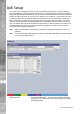
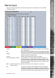
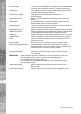
Alarm Input
This menu allows conguration of the alarm settings, refer to ‘Installing the Unit’ for hardware
installation guidance.
Number This identies which input is being congured. The unit supports
19 on-board alarms.
Ena Each input must be enabled to function. If the input is not enabled
and an alarm is received, the unit will not acknowledge the alarm.
Module The alarm contacts are connected via modules. Select the module
that the contact to be congured is in.
Contact Select the Contact within the module to congure.
N_O (Normally Open Contact) N_O indicates the non-alarm state of the input. Tick the N_O
checkbox to set the corresponding input to Normally Open. The
alarm will then trigger when the input is closed (shorted). If left as
Normally Closed (the default setting), the alarm will trigger when
the input is opened.
Note: If EOL alarms are to be used, this option should not be selected i.e. leave set as
Normally Closed.
EOL The End Of Line (EOL) option enables the inputs to detect any
changes in the electronic input resistance. A change outside the
expected values will result in a Tamper Alarm (short circuit or open
circuit) being detected and the system switching to alarm mode.