
Operating instructions

Dedicated Micros ©2010
173
SD Advanced
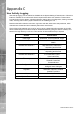
Appendix A
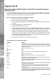
Alarm & Relay Pin Outs
Using Serial Ports
It is possible to connect a variety of telemetry cameras to the unit, using the following table as a
guide to the serial port connections.
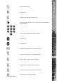
1
5
6 9
RS485 Connectivity (2 wire) (Serial 3, 4)
Pin Description
1 RS485 + (A)
9 RS485 - (B)
5 Shield (GND)
RS232 Connectivity (Serial 1, 2)
Pin Description Desc
1 Data Carrier Detect DCD
2 Receive Data RX
3 Transmit Data TX
4 Data Terminal Ready DTR
5 Ground GND
6 Data Set Ready DSR
7 Ready to Send RTS
8 Clear to Send CTS
9 Ring Indicate RI
RS232 Connectivity (Serial 3, 4)
Pin Description Desc
2 Receive Data RX
3 Transmit Data TX
5 Ground GND
7 Ready to Send RTS
8 Clear to Send CTS