
Operating instructions

Dedicated Micros ©2010
11
SD Advanced
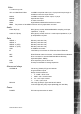
Video
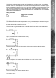
8. 16 & 32 way units
VID1 to VID8/VID16/VID32 75Ω BNC composite video input, 1V pk-pk with loop through 1V
available on 8 and 16 input variants
MON A 75Ω BNC composite monitor output, 1V pk-pk
MON B Spot Monitor output
MON A S Video Connection
HDMI High-Denition Multimedia Interface connector
Note: The position of the HDMI connector will vary dependant on model
Audio
Audio IN (Dual) RCA (phono) socket, 8KHz/16KHz/22KHz sampling 75Ω input
impedance, 1V pk-pk
Audio OUT (Dual) RCA (phono) socket, line level <100Ω output impedance,1V pk-
pk amplication required
Data
SERIAL 1 RS-232 (3 wire & 9 wire)
SERIAL 2 RS-232 (3 wire & 9 wire)
SERIAL 3 (PTZ) RS-485 (2 wire & 4 wire)
SERIAL 4 (PTZ) RS-485 (2 wire & 4 wire)
USB 2x USB2.0 connectors
IR Infra-Red Input connector for IR Remote Control Extender
NET RJ45 Ethernet network connector, 10/100 Mb/s Ethernet Network
KBD RJ12 connector for use with Dedicated Micros telemetry
keyboards (KBC1, KBC2)
EXP RJ12 expansion port for future use
SATA E-Sata port available for storage expansion
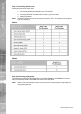
Alarms and relays
ALARMS IN Via 25-way (female) D Type 24V 200mA
20 general alarm inputs
Range of Alarm states are:
i. 0 – 800R = Short circuit
ii. 800R – 2K = closed contact
iii. 2k – 12k = open contact
iv. > 12K = open circuit
RELAYS Via 9-way (female) D Type rated at 24V 200mA
4 onboard light duty relay output (500mA@ 12V-48V Max)
Power
POWER IEC mains power socket & switch