SD Advanced Installation and Operation Guide
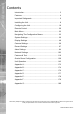
SD Advanced Contents Introduction............................................................................ 3 Features................................................................................ 4 Important Safeguards............................................................ 6 Installing the Unit................................................................... 8 Configuring the Unit............................................................. 18 Remote Control.....................................
What is the… SD Advanced ? SD Advanced Introduction A comprehensive digital recording solution, the SD Advanced is a stand-alone high performance recording system offering reliable, networked, scalable CCTV at an affordable price. Its size and design make it the ideal desktop solution and perfect for installations were high record rates and network capabilities are required.
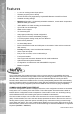
SD Advanced Features • 8, 16 or 32 analog camera input options • Telemetry support (Coax & Serial) • All DVR functions fully supported by Keyboard/IR Remote Control/Front Panel • Scalable recording settings • MultiMode Recording - Dynamically-switchable resolution, record-rate & compression (MPEG4/JPEG) per camera • JPEG, MPEG-4 or H264 recording and transmission • Up to 4TB of on-board storage • HDMI monitor support • I.
MAP Users can now navigate around their CCTV installation using a graphical map. Selecting the relevant camera from the map will instantly connect the user to that cameras image stream. With the ability to load bespoke map images and floor plans to reflect their installations, the Maps feature is ideal for quickly identifying camera locations around a site or CCTV network. SD Advanced Point&go provides the user with easy to use, fast, accurate telemetry control via an attached monitor.
SD Advanced Important Safeguards Read Instructions All the safety and operating instructions should be read before the unit is operated. Power Sources This unit should be operated only from the type of power source indicated on the manufacturer’s label. Servicing Do not attempt to service this unit yourself as opening or removing covers may expose you to dangerous voltage or other hazards. Refer all servicing to qualified service personnel.
If this product is marked with the CE symbol it indicates compliance with all applicable directives. Directive 89/336/EEC. A ‘Declaration of Conformity’ is held at Dedicated Micros Ltd., SD Advanced CE Mark 1200 Daresbury Park, Daresbury, Cheshire, WA4 4HS, UK. Laser The unit supports an integrated CD-R/DVD-R writer, the following are additional warnings associated with installing and operating the CD-R/DVD-R writer, please pay particular attention to this information.
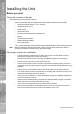
SD Advanced Installing the Unit Before you start Check the contents of the box The following items are included in the box: Remove all items from the packaging and check the items listed below are present.
Please ensure the following are available and have been tested prior to the installation: • Mains point • Network point • Network cable • Active video signals i.e. at least one working camera feed • PC with CD ROM drive and connection to the same network as the DVR (Recommended). SD Advanced Electrical Connections Quick Overview of SD Advanced Record Settings The SD Advanced provides as default: Consistent recording duration and smooth motion video per camera regardless of the number of cameras.
SD Advanced Installation Front Panel connections Data DVD-R USB LED Internal CD/DVD-R drive (located under hinged flap) USB2.0 connector (located under hinged flap) Green - Unit working normally No LED - Power Failure Live - Unit is in Live mode when lit. Play -Unit is in Playback mode when lit. Spot - Spot (MON B) monitor is being controlled Record - Unit is recording video to the internal hard disk.
8.
SD Advanced Installing the SD Advanced Unit This procedure shows the sixteen camera input version. Step 1 Connecting Analog Video The SD Advanced supports up to 8, 16 or 32 connected analog Video Inputs (dependant on model) via the 75Ω BNC connectors. Connect cameras to the video inputs, starting from input 1. 5.12 Step 2 Monitor The unit supports a main monitor via ‘HDMI 1’ and BNC ‘A’. A spot monitor can be connected via BNC ‘B’.
SD Advanced Step 3 Connecting Audio The SD Advanced supports two channels of bi-directional audio, accessible through NetVu ObserVer. Connect the audio equipment to the phono sockets AUDIO IN and AUDIO OUT. The audio channel defaults to recording camera 1. The following modes of operation are supported: • Challenge – intruders from an RVRC. • Listen – to local audio from a site at the RVRC. • Record - local audio from a site with the video.
SD Advanced DHCP works by assigning an IP address at initial connection to the network. It is possible however that this IP address can change without notification i.e. following power failure. It is therefore recommended that the unit be allocated a fixed IP address. A fixed IP address can be assigned via the Configuration Menu pages:Network Settings->Network->IP Address.
Relay Connector Pin 1 - 20 21-25 Alarm Input Connection 1-20 Earth Common SD Advanced The SD Advanced supports 20 normally open/closed tamper proof alarm inputs, or one Global keyswitch input with camera specific inputs configurable as entry/exit alarms. The alarms support tamper proof detection using 1k in line and 5K end of line resistance. The unit detects short circuit, open circuit and contact closure.
SD Advanced Step 7 Connecting Serial Ports Serial ports have three main uses: Note: 1. Connecting twisted pair telemetry for PTZ cameras. 2. Providing text data recorded with the video e.g. Point of Sale. 3. Debug operations. Telemetry cameras should be connected to Serial 3 and 4. Text data can be retrieved from any serial port. RS232 RS485 5.16 6.1 Step 8 Connecting a Keyboard The SD Advanced supports Dedicated Micro keyboards DM/KBC1 and DM/KBC2.
A DM Oracle, 2040 or 2060 Dome can be connected via either co-axial telemetry or RS485 twisted pair. If using co-axial the address switches should be set as: Blue switch - F Yellow switch - D If the dome is being connected using RS485, the dome address should be set according to the camera number of the SD Advanced.
SD Advanced Configuring the Unit The unit can be configured either on the local monitor or over the network using a PC with Internet Explorer or similar browser. Both have near identical menu interfaces. Accessing the menus on a local monitor The Configuration pages can be displayed on a local monitor. Note: When connected, press the MENU button on the IR Remote Control.
The unit can be configured using the webpages. To access these: 6.13 1. Launch Internet Explorer (or similar web browser package). 2. Type the URL for the unit (IP or DNS address). 3. The Opening menu page will be displayed.
SD Advanced Remote Control The IR Remote Control offers all the control functionality required to navigate the menus. Note: Not all buttons on the IR Remote Control are relevant for the Unit. Key Button Switches the Remote Control to ‘TV’ mode and sends codes understood by common TV sets. Switches the Remote Control to ‘DVR’ mode. Note the DVR mode is the default mode of operation. Toggle the speed of PTZ camera movement (two speeds available).
Use the Directional and OK buttons to navigate through the menu screens and accept changes. Also use for PTZ telemetry control of cameras. Use the Softkeys (Red, Green, Yellow, Purple) to directly access the corresponding function displayed on the menu screen. The Number pad should be used to select specific cameras and preset positions when available. Dedicated Micros ©2010 SD Advanced Use the Playback buttons to interrogate recorded images.
SD Advanced Main Menu When first accessing the unit, the main menu will be displayed. This menu allows access to the Configuration menus, the Viewer menus and also several Download options. Note: The Download options will only be available if viewing remotely via an IP connection. Select the Configuration menu tab to access the unit’s Configuration menus. Refer to ‘Navigating the Configuration Menus’ for further guidance. Select the Event Search tab to access the unit’s Event Search function.
When accessing the configuration menus, the menu tree will be displayed. The configuration pages are navigated using the menu tree (displayed on the left of each page). Selecting one of the menu options will display the relevant page. Associated sub-menus will then be available. SD Advanced Navigating The Configuration Menus Relevant menus can also be accessed directly from other menu screens via the coloured softkey options shown at the base of each menu.
SD Advanced Using the IR Remote Control Press the MENU button to access configuration menus via a connected local monitor. The menu will have a red indicator highlighting the first option. Select a main menu heading to open a drop down list of further sub-options. Press the Down Directional button to highlight the next menu option, press OK to open the highlighted menu. Press the Right Directional button to highlight the first editable parameter on the screen.
Numeric or text data is entered using the on-screen Virtual Keyboard (Arrow Key Editor). To display the Virtual Keyboard, navigate to the relevant text input box using the Directional buttons and double press the OK button twice on the IR Remote Control or Front Panel Interface. The Virtual Keyboard is displayed. Use the Directional buttons to move between characters, use the OK button to select a character. Select ‘Submit’ to enter details, press ‘Cancel’ to exit without entering any text.
SD Advanced System Settings The menus under the System Settings heading allow the unit’s core settings to be viewed, changed and the system software upgraded. The System option displays details about the unit including the IP address, unit serial number, MAC address and software version. The Unit Status page displays information about the unit’s operating condition, shows how long the unit has been operating and the reason for the last reset. It also shows camera status and displays any failed cameras.
6.13 This menu shows the general information about the unit including the version of software installed, the unit’s serial number and the allocated DHCP IP address. Product Descriptor Serial Number PCB Serial Number Product Code Earliest Recording System Name Video Standard Number of Cameras Global PPS Video Storage Gbytes MAC Address IP Address Dedicated Micros ©2010 SD Advanced System Details the product model. Identifies the serial number of the specific unit.
SD Advanced Sub Net Gateway Software (Red) This is the subnet of the network where the unit is located. This is the IP address of the default gateway (router) assigned by the DHCP server. Select this option to display installed software information (see below). Software Menu Software Revision Codec Revision Webpage Revision Framestore Revision PC Apps Revision This identifies the version of software the unit is running. This identifies the codec version the unit is running.
This menu details information regarding the status of the unit, notably the total time the unit has been operating and the time since its last reset. Status log information can also be exported via the ‘Export Logs’ option to either a CD-R/DVD-R or a USB device. Time since last reset Total running time Reset code Restart reason Codec Cameras Connected Recording Cam Status Dedicated Micros ©2010 SD Advanced Unit Status Details the time since the unit was last reset.
SD Advanced Alarm Status This menu details information regarding the status of the unit’s alarm contacts, alarm zones and relay outputs. Alarm Contacts/Zones/Relay Outputs Alarm Contacts, Alarm Zones and Relay Outputs that are in an ‘active’ state are shown light green. ‘In-active’ ones appear dark green (not illuminated).
This menu allows access to numerous system information pages. Select the an icon to view the relevant pages. System Information Software Reference General Information Record Details Dedicated Micros ©2010 SD Advanced About Select to open the System menu. System information will be displayed. Refer to System Settings->System for guidance on the information available. Select to open the Software Reference menu. Software information will be displayed.
SD Advanced Turbo Mode Profiles Select to open the Turbo Mode Profiles menu. This menu provides detailed information on the camera record settings when the unit is configured to operate in Turbo Mode. Note that when the unit is not operating in Turbo Mode, no information will be displayed. Refer to the Profile Record menu (Record Settings->Profile Record) for further information on the Turbo Mode function. Codec Loading Select to open the Codec Loading menu.
This menu allows the system language to be set. Changing the System Language will effect all menu pages. If required, the language can also be changed for the current session only. SD Advanced Language System Language Select to change the system language setting. Reset (Red) Select to reset the unit. Note: The unit MUST be reset to implement system language changes. Refer to System Settings->Maintain for guidance on resetting the unit.
SD Advanced Time and Date This menu allows the time and date to be set on the unit. Required timezone information can also be established and the unit time synchronised to that of the PC being used to view the webpages. System Time Current Time Zone Time Format The current system time and date is displayed. Displays the currently selected time zone settings. As default, the time displayed is in 12 hour format. This can be changed to 24 hour if required.
Displays the system time of the PC currently being used to view the webpages. Sync Time (Blue) Use this button to synchronise the time of the unit to that of the PC being used to view the webpages. Note: The PC Time and Sync Time options will only be available if viewing the menu via the webpages.
SD Advanced Serial Ports This menu allows configuration of the unit’s Serial ports. Refer to ‘Installing the Unit’ for installation information. Serial Port Port Config These are the four serial ports available. The serial ports can be configured to specific uses.
Note: This is a drop down list of serial telemetry protocols supported by the unit. Refer to ‘Appendix G’ for a full list of supported telemetry protocols.
SD Advanced Audio The Audio menu allows settings for the bi-directional audio channels to be edited. Audio can be recorded from camera inputs via input 2. Challenge audio i.e. originating from an Operator using NetVu ObserVer at a Remote Video Receiving Centre (RVRC) can be recorded via input 1. This combined audio is then available on Audio Output 1. Refer to ‘Installing the SD Advanced for audio hardware installation information.
This option allows the Record Gain level to be set. This is the base setting from which the AGC (Automatic Gain Control) will operate. Select from 1 to 15. The default and recommended setting is 15. Playback Volume Select a volume setting between 1 to 64 for audio playback. Record AGC Select this option to activate the AGC function. AGC helps produce a better quality recording by removing background noise/distortion. Record uncompressed Select this option to record audio in an uncompressed format.
SD Advanced Features These menus enables the activation of numerous system features. Features are grouped within four sub-menus: System, Network, Video and Other. System User Logging Enable this option to activate User Logging. Refer to ‘Appendix C’ for further information regarding the User Logging function. Enable External Modules Select to enable any connected RS485 alarm modules.
Note: Select this option to enable automatic FTP downloads to upgrade the unit and/or the webpages, refer to ‘Network Settings-FTP Download’ for more information. When de-selected here, the ‘Automatic FTP Download’ menu will no longer be displayed in the menu tree. Webcam Support Camera Masking Dedicated Micros ©2010 Select this option to activate the Webcam function.
SD Advanced Network Secondary Web Port Telem UDP Port Selection 42 If the default port setting for web serving has already been allocated, it is possible to configure a second port number i.e. the secondary web port can be set to 8000 if the default web port (80) is blocked by the network or firewall. Select ‘Automatic’ to enable the unit to select a suitable port for telemetry purposes. Select ‘Default’ to use the default port settings (1025).
SD Advanced Video Detected Video Standard Deinterlace mask Comb Filter Disable Transcoding Partial Full Duplex Dedicated Micros ©2010 The unit automatically detects the video standard being used i.e. PAL/NTSC. When Enabled, this option will improve the appearance of moving objects by applying a deinterlace mask that minimises the comb effect that can be visible when recording high motion scenes in 4CIF mode. It is recommended that this option be enabled when recording in 4CIF mode.
SD Advanced Other Auto Update Web Variables Configures the unit to update all system variables required for an automatic upgrade without requiring confirmation. Do not check this box if you run a customised applet. Enable Event Search Select to enable the Event Search option. When enabled, the option will appear within the Configuration Menu tree. Refer to ‘Navigating the Configuration Menus->Event Search’ for further details.
This menu allows the unit to be reset and a software upgrade to be performed via an inserted CD-R/ DVD-R or a connected USB device. Current unit settings can also be saved for future use and previously saved settings restored. SD Advanced Maintain Configuration Default (Green) Select to return the unit to its factory default settings. Note: Selecting the Default button will cause the system to reboot. Save (Purple) Restore (Blue) Note: Select to save current unit settings to the selected media.
SD Advanced 46 Server Reset (Red) IMPORTANT: Note: Select to cycle the power to the unit. To upgrade the unit, insert a media device containing relevant software upgrades and select ‘Reset‘. For the latest software upgrades, please refer to the Dedicated Micros website: www.dedicatedmicros.
This menu enables installed PowerScripts to be activated/deactivated on start-up. Use the tickbox(es) to select/deselect installed PowerScripts, then select Save (Green). A system reset will be required for the changes to take affect. Note: SD Advanced PowerScript Mgmt Changes this page will alter the ‘Default.C’ file. If you already have a custom PowerScript on your unit which uses Default.C, please contact Dedicated Micros Technical Support for guidance Tel: +44 (0) 845 600 9502 for further guidance.
SD Advanced Display Settings The menus under the Display Settings heading allow the unit’s Viewer display settings to be altered and User Account details to be viewed and changed. The Remote Monitors page allows monitors not physically connected to the unit to view camera images received by the unit. The Viewer Defaults page allows the Viewer menu settings to be configured. The Display page controls how the local monitors present information.
This menu allows monitors not physically connected to the unit to view camera images received by the unit. The IP address of the server connected to the monitor (or video wall) is required. Cameras can then be selected via the remote monitor SD Advanced Remote Monitors Up to 16 remote monitors (or video walls) can be configured. Enter the IP address of the server connected to the monitor.
SD Advanced Viewer Defaults This menu allows configuration of settings for the Viewer function. Refer to ‘Operating The Viewer’ for more information regarding this feature. Default settings can be configured for accessing the Viewer function via a local monitor and also remotely via a network connection. Local settings also determine the quality of video streams received from a remote client i.e. in Remote Monitor operation.
When accessing the Viewer function, select the camera image which will initially be displayed. If one of the multi display formats has been selected via the ‘Startup Multi Display’ option, the camera channel selected here will be displayed in first (top left) position. Subsequent camera channels will be displayed in sequential order. Video Output mode Select the display output that best suits the viewing monitor. Typically PAL Default is most suited for a CRT monitor.
SD Advanced Display This menu allows configuration of monitor settings used when viewing camera images and text data. Main monitor text Background Colour Text Colour Sequence Dwell (secs) Sequence main on startup Enable custom segment setup Camera selection switches to full screen 52 It is possible to select text to be displayed on the main monitor. The text displayed will include; time, date, mode of operation (Set, Unset or Override), camera number and camera title.
Spot Sequence Dwell Spot Sequence Setup Select All (Blue) Dedicated Micros ©2010 It is possible to select text to be displayed on the spot monitor. The text displayed will include; time, date, camera number and camera title. The spot sequence dwell time can be set from 1 to 99 seconds. The dwell time is the period a camera’s images are displayed on a connected spot monitor before switching to the next camera in the sequence. All of the unit’s camera input channels are shown.
SD Advanced Map Config This menu allows images to be imported and used as maps that can be displayed in the Viewer Menus. The map can then have hotspots added to allow quick navigation to individual cameras. An overview ‘System Selection Map’ can also be added to navigate between different systems. Configure Map Graphic Location Map Screen Offset Camera Select Activate Hotspot Hotspot Radius Increment by Decrement (Red) Increment (Green) 54 Leave as ‘Local System Map’.
Use to position the centre of the hotspot along the X axis e.g. entering 20 would place the hotspot centre 20 pixels from the left edge of the map. Hotspot Y coord Use to position the centre of the hotspot along the Y axis e.g. entering 20 would place the hotspot centre 20 pixels from the bottom edge of the map. Note: The hotspot can also be positioned by clicking directly on the map.
SD Advanced Map Data The Map Data menu allows Map Config data to be Imported/Exported. This enables map data to be saved and stored for future use, or used between multiple units. Note: The Map Data menu will only be available when viewing the menu pages remotely i.e. via the webpages. To save map data, highlight and copy all text displayed in the Map Data text window, then save this data as a text file. To import data, copy relevant text from an external location and paste into the Map Data text window.
The unit can protect configuration procedures by limiting access via usernames and passwords. SD Advanced User Accounts Account Types The available account types for which users and passwords can be assigned privileges are: • Admin FTP Assigning username and password requirements for the Admin FTP function will limit access to the unit via an FTP connection.
SD Advanced • Menu Configuration Assigning Menu Configuration access privileges will limit access to the Configuration menus when viewed locally. When implemented, the user will be prompted for a username and password before access to the Configuration menus (via the main menu) will be granted. • Local Users Assigning Local Users access privileges will limit access to the Viewer pages for local users.
The Camera Settings menus allow configuration of cameras connected to the unit. Refer to the individual menus for further details. The Camera Setup page allows the quick configuration of all connected local camera channels (with a dynamic preview available). The Camera Overview menu details the general settings assigned to each of the local camera channels.
SD Advanced Camera Setup This menu allows the configuration of active camera channels. IMPORTANT: Note: The menu options displayed will differ depending on the camera ‘Type’ and ‘IP Mode’ selected. Ideally any setup options available locally on the camera should first be used to best obtain a suitable image quality. Mono/Colour Camera Camera Camera Nuisance Count Title Type IMPORTANT: Fail Rep 60 Select a camera channel for review and adjustment. Assign a recognisable name to the camera.
Telemetry Default to preset Colour Brightness Dedicated Micros ©2010 The unit will automatically terminate the camera input with 75Ω. This should be disabled if the video feed is looped through to another device. If a telemetry capable camera is connected, the appropriate control protocol should be selected from the accompanying drop down list. Refer to ‘Appendix G’ for details of supported telemetry protocols.
SD Advanced IP Camera The following menu will be displayed when ‘IP Camera’ is selected. The menu allows the configuration of connected IP Cameras (cameras connected directly to a network broadcasting a digital video stream from an IP address). It can also connect to other NetVu Connected DVRs and treat one of the network feeds from that DVR as a digital video stream.
If a telemetry camera has been assigned a preset position, select the chosen preset position here. Also enter the time period (in minutes) of inactivity which will result in the camera moving to its preset position. Refer to Viewer menus->Program Page for guidance on assigning camera presets. Colour Select a colour value from -8 to +8 via the slidebar or enter a number directly into the accompanying textbox.
SD Advanced 64 Camera Overview This menu details the general settings assigned to each of the local camera channels. To edit the settings assigned to any of these cameras, select the ‘Setup’ option. This will open the Camera Setup menu, refer to Configuration menu->Camera Setup for further details.
The IP Streams menu allows the selection of High, Medium and Low resolution settings for video sources originating from a network based source i.e. IP Server. These streams are configured on the remote device. This feature is predominately intended for use with 3rd party IP camera streams (connected via the 3rd party IP camera unlock feature). Note: There is only normal ‘non event’ recording for connected IP cameras.
SD Advanced 66 Res Note: For both MPEG and JPEG recording, select either High, Medium or Low quality resolution settings. To view a local third party IP camera ‘live’, IP recording should be set to MPEG. IP Camera (Yellow) Select to open the IP Camera menu.
The Record Settings menus allow configuration of the unit’s record functions. Record settings can be configured for normal operation, on alarm, by schedule and for set holiday and weekend periods. Selected video data can be saved and protected. Refer to the individual menus for further details. The Record page allows the basic Recording settings to be edited. The Profile Record page allows the recording configuration to be based on specific priorities.
SD Advanced Record The unit has a range of pre-defined configurations available. As standard the unit can record at 6pps MPEG4 for up to 120 days (dependant on model). Alternatively the unit can be configured for 2pps JPEG recording on each camera or for MultiMode operation (note that this will result in the record duration being determined by the time period the unit is in alarm). Days Recording Displays the record duration possible using the current configuration.
It is possible to set the unit recording configuration based on specific priorities. The MultiMode recording feature offers the ability to set different recording rates, resolutions and compression formats across unset, set and override modes for each individual camera. By varying the quality, bit rate and file size of recorded images, the MultiMode function enables the recording capabilities of the unit to be greatly increased. The Profile record menu can be accessed in a Simple format or in Advanced mode.
SD Advanced Simple Record Menu View IMPORTANT: Switch to the Advanced Profile Record menu. If Turbo mode is ‘Disabled’ and record settings have been configured which will exceed the unit’s Codec performance threshold. A warning message will be displayed informing the user that the ‘Unit needs to be in turbo mode’.
Note: Note: Shows the recording quality that will be used by the camera during an Alarm or Event. Note that Set and Override schedules will be used only when Timed Schedules are applied. Refer to the ‘Schedules’ section for further details. When Turbo mode is selected, there will be only ONE configurable Record Profile across ALL cameras. The unit then matches the live transmission rate to the configured record rate. This enables a ‘doubling’ of performance.
SD Advanced Advanced Record Menu View Switch to the Simple Profile Record menu. Note: When Advanced Record settings have been changed, it is not possible access the Simple Record menu until the newly configured Advanced Record settings have been applied. To do this, open the Record menu and select the ‘Save’ option. It will then be possible to return to the Profile Record menu and access Simple Record.
Shows the recording profile used by the camera if no Timed Schedules are applied and the camera is operating under Normal (non Event) conditions. Refer to ‘Schedule’ for further information. Unset/Set/Override Event Shows the recording quality that will be used by the camera during an Alarm or Event. Note that Set and Override schedules will be used only when Timed Schedules are applied. Refer to ‘Schedule’ for further information.
SD Advanced JPEG Pre Trigger This menu enables configuration of the pre trigger feature (for cameras recording JPEG mode only). When enabled, the pre-trigger feature will buffer and store alarm recording prior to an event trigger. Channel Only those camera channels set to record in JPEG mode will be available for configuration. Pre-Trigger (JPEG) Enabling the Pre-Trigger feature will buffer and store alarm recording prior to an event trigger (in JPEG format).
This menu allows the Timer Function to be configured. The Timer Function enables the unit to automatically be put into set/unset mode at specific times on specific days. This can help reduce unnecessary alarm triggers. When the unit is in Set or Unset mode, combine with different recording qualities and rates under normal and alarm conditions for a high degree of control in a range of situations. Note: If Keyswitch is Enabled, the Day Time and Night Time options will not be displayed.
SD Advanced 76 Keyswitch-N/O Keyswitch EOL Select whether the Keyswitch is to be normally open (UNSET) Select to configure the Keyswitch for EOL. The End Of Line (EOL) option enables the Keyswitch to detect any changes in the electronic input resistance. A change outside the expected values will result in a Tamper Alarm (short circuit or open circuit) being detected and the system switching to alarm mode.
This menu allows a user to temporarily switch the unit’s system state into set/unset/override mode. The user will be required to enter their name and also the intended override duration. The action will be logged. Note: Refer to the Schedule menu for details of how to configure Set, Unset and Override modes: Record Settings->Schedule. SD Advanced RVRC Current System Time The unit’s current date and time information will be displayed. This will be logged with any override action.
SD Advanced 78 Enter Your Name Force UNSET(Green) Force SET (Yellow) Force OVERRIDE (Blue) Enter your recognised user name. This will be logged. Select to switch to Unset mode. Select to switch to Set mode. Select to switch to Override mode.
This menu allows the unit to be automatically switched to Override mode for individual days i.e. public holidays or during a weekend (or any defined period). SD Advanced Holiday & Weekend Holidays Enter a date and press the Add button. The date will be added to the Holiday list. To delete, highlight and select Delete. Weekends Select ‘Enable’ to activate the Weekend function. Set mode will now be active for the dates outlined below. Start Select a Start day and time for Weekend mode.
SD Advanced Protect Video This menu allows the unit to automatically protect and retain recorded data. Previously saved data can also be unprotected. Enter a start and end time and select ‘Reload List’ . All saved video files from the chosen time period will be shown in the upper textbox. These recorded ‘PAR’ files can then be selected and protected via their accompanying checkboxes and the Protect option. Selected video files can also be unprotected via the Unprotect option.
List To Date/Time Dedicated Micros ©2010 This selects all the available video files. This dialog box allows a search to be made within the protected video list starting from a specific Time and Date. This dialog box allows a search within the protected video list to conclude at a specific Time and Date.
SD Advanced AoE Setup This menu allows configuration of the units ATA over Ethernet (AoE) function. AoE is a network protocol designed for simple high-performance access of storage devices over Ethernet networks. Importantly the external storage device must be located on the same network as the unit. AoE does not rely on network layers such as IP and TCP, making it non routable i.e. routers cannot be used to forward a packet across disparate networks.
Dedicated Micros ©2010 Available AOE Devices - Any devices in this panel are available on the network. They can be added to the storage capability of this unit by ‘claiming’ the storage. Unavailable storage is listed as Owned. Claimed storage capacity can be ‘released’ in the top panel.
SD Advanced Alarm Settings The Alarm Settings menus allow configuration of the unit’s alarm functionality. Individual alarm inputs and alarm zones can be configured. Global relays can be activated and the Activity grid set up. Refer to the individual menus for further details. The Alarm Input page allows configuration of alarm channels. Up to 19 alarm channels are available. The Zone Input page enables the configuration of alarm zones. Up to 32 separate alarm zones can be created.
This menu allows configuration of the alarm settings, refer to ‘Installing the Unit’ for hardware installation guidance. SD Advanced Alarm Input Number This identifies which input is being configured. The unit supports 19 on-board alarms. Ena Each input must be enabled to function. If the input is not enabled and an alarm is received, the unit will not acknowledge the alarm. Module The alarm contacts are connected via modules. Select the module that the contact to be configured is in.
SD Advanced 86 Pulse Ext (s) A pulse extension is used to prevent double triggers on a single alarm. The pulse extension time starts on an alarm trigger. If that contact is triggered again after the first alarm has finished but within the pulse extension, the second trigger will not restart the alarm, but will extend the current alarm duration. Enter the time in seconds for this extension. Nuisance This is a repetitive detector value.
This menu allows the configuration of established alarm zones. A single or multiple trigger can be used to generate an alarm. It is possible to allocate up to 32 alarm zones to carry out a combination of actions. Use these options in conjunction with the Zone Actions menu. SD Advanced Zone Input Entry timer This is the number of seconds allowed for the user to enter the zone and disable the alarms. If the alarm is not disabled within this period the alarm will be triggered.
SD Advanced Alarm Duration sec Zone Input Rule Input Zone OR Input Zone AND Input Zone NOT Input Alarm 24Hr Entry Route Zone Exit route Zone Exit Terminator Entry Initiator Enable in Unset Enable in Set Enable in Override 88 This is the minimum time period in seconds (from the start of the alarm) that is protected from being overwritten. This time will include the alarm trigger, the pulse extension and any post alarm recording. It will not include pre-alarm images.
This menu allows actions to be allocated to individual alarm zones; Primary and Secondary cameras can be allocated to the zone and actions undertaken following alarm activation. This page should be configured in conjunction with the Zone Inputs menu. Zone Alarm Colour Secondary Cameras Create Database Entry Alarm Relay Profile Change Play Audio Alarm Reporting Archive Dedicated Micros ©2010 SD Advanced Zone Actions Select a zone (alarm) to configure.
SD Advanced Add Still Image Email Image Protect alarm Images Switch Spot Monitor Goto Preset Email Reporting Alarm Rate Change VMD/Activity Inhibit System Set Enable Buzzer Relay Relay Duration Alarm Image Snapshot Delay This will record a still image of the trigger along with the standard recording. This can then be sent on to an external destination. If this option is selected, a JPEG will be added to the reporting email (if Email Reporting is selected).
SD Advanced Zone Actions Camera Zone Primary Camera Secondary Cameras Preset Camera Preset Dedicated Micros ©2010 Select a zone (alarm) to configure. This allows a camera to be assigned as the primary camera associated with the Alarm Zone. The primary camera will be displayed when an alarm in this zone is triggered. This setting gives the facility to assign additional cameras to the zone. These cameras will become part of the alarm sequence shown in the Viewer menus when the alarm zone is triggered.
SD Advanced Masked Cam Detection The unit has the capability to identify if a video input has been covered (by hand, spray paint, etc.) to prevent video images being viewed and recorded. The Camera Masking option identifies normal levels of contrast and uses them as a base line. It then compares these against a user defined minimum contrast level. If the video input goes below this user defined level an event is generated on the unit.
On Camera Masked/Unmasked Dedicated Micros ©2010 Defines the contrast threshold the system uses to define that a camera is masked. Different cameras have different characteristics, There is only the option to add an entry into the database in Simple Activation. Select Zone Activation for more options.
SD Advanced Zone Activation On Mask On Clear 94 Defines the Zone trigger that will be activated when the view is masked. Defines the Zone trigger that will be activated when the view is unmasked.
This menu enables response configuration following activity trigger on a selected camera channel. SD Advanced VMD/Activity Response Setup VMD Pulse Ext The pulse extension extends the trigger period to avoid double triggers of VMD occurring, i.e. If a second incident of VMD is received, after the first alarm is finished but within this period, the unit will not create a new event. Channel Select the camera input for configuration from the drop down list.
SD Advanced Profile Change Alarm Reporting Alarm 24Hr Add Still Image Protect Alarm Images Alarm Relay Email Image Enable in Unset Enable in Set Enable in Override Select to enable the unit to switch from Normal to Event recording following alarm activation. This must be enabled for the unit to automatically connect on alarm. This will ensure that Activity Detection is permanently enabled on this camera channel. This will record a still image of the trigger along with the standard recording.
The unit supports Activity Detection on all video inputs. It enables cameras to automatically detect any movement/changes within the video scene; this can trigger a number of operations such as FTP alarm notification and an increase in recording rate. A still image of the selected camera will be shown in the Grid Editor screen. To establish an Activity zone, edit the cells displayed across the image. This option should be used in conjunction with the Zone Inputs and Zone Actions menus.
SD Advanced Grid Editor Reload Img (Red) Set All (Green) Clear All (Yellow) 98 Use the Grid Editor by placing cells in areas of the camera view where movement will trigger an alarm. To enter cells navigate across the image via the Directional buttons of the I.R Remote Control). If viewing on a local monitor place a cell by pressing the OK button. If viewing via the webpages, use the mouse to navigate across the image, use the left mouse button to place a cell.
The unit supports VMD (Video Motion Detection) on all video inputs and allows cameras to automatically detect if there is any movement/changes within the video scene. Note: Video Motion Detection enables a greater degree of control over detection settings and configuration than the Activity Setup function. Each of the 16 VMD Zones can be directly sized and configured to suit specific requirements. VMD can only be accessed and configured remotely via the webpages.
SD Advanced 100 Mode The zone mode identifies when the reference image is taken for triggering VMD. The options are: Normal - The reference image is updated approximately every second. This will only allow small changes in the scene without triggering. Last trigger The reference image is only updated when the VMD is triggered and is best used under controlled lighting, i.e. so there are no false triggers due to ambient light changes.
This menu allows configuration of the default relay actions supported on the unit. The unit supports four onboard relay connections and global relay settings. This global relay can be triggered under specific conditions i.e. on receipt of any alarm or notification of Activity Detection.
SD Advanced 102 Contact Module Specifies which Relay will be triggered when the associated alarm is received When connected, additional modules will be available i.e. 485 Bus module. These modules can then be activated following relay activation.
The Network Settings menus allow configuration of the unit’s network functionality. Key network settings can be established such as ‘fixing’ the unit’s IP address and maximum transmission rate. Email, remote reporting on alarm and FTP download can also be configured. Refer to the individual menus for further details. The Network Settings page allows configuration of the unit’s network connections such as the name assigned to the unit and its IP address.
SD Advanced Network This menu allows additional network settings to be configured if required. Server Name IP Address Sub Net Gateway Primary DNS Max Transmission Rate Tx Image Buffers Ethernet MTU bytes Mx Transmission Timeout ms PPP Base IP PPP Idle Line Timeout s 104 This field can be edited to allocate a name to the unit. This would be used if accessing the unit via a Domain Name Server (DNS). This is the IP address allocated to the unit. This is the subnet of the network were the unit is located.
Hangup After Alarm Dedicated Micros ©2010 If for any reason the PPP connection is lost, this is the time (in minutes) before the unit will be forced to drop the PPP connection. Select to close the network connection following transmission of alarm data.
SD Advanced Live Transmissions The unit transmits live images using JPEG or MPEG formats. The NetVu Connected remote viewing software will use the settings configured on this page as the defaults for JPEG & MPEG; High, Medium and Low settings. Filter by The resolutions available for selection will depend on the camera types connected i.e. Standard Resolution or Megapixel Resolution and whether Turbo Mode has been activated via the Profile Record menu (Record Settings->Profile Record).
When ‘Filter by Turbo mode’ as been selected; all High LAN options will be auto-configured to match the profile record settings allowing for maximum record performance. High LAN will no longer be available for configuration of local analogue cameras or third party IP cameras. Select the Turbo Profs (red) option to view Turbo mode Profile Record/Transmission settings. Comp Res Size_rate PPS MPEG Type MPEG Quality I Frame Ratio Settings can be established for JPEG and MPEG compression.
SD Advanced Multicast Setup The Multicast page allows recordings from the unit’s camera input to be forwarded to a port address; enabling multiple viewers to view live data using a suitable media player without the need to directly connect to the unit. In multi viewing scenarios, the demands on the unit are significantly reduced; improving overall performance. This system has been validated using the ‘Videolan VLC media player for MS Windows.
Select the multicast forwarding method. Select from ‘SAP’ (to use session announcement protocol operation), ‘HTTP’ (to use cgi control operation) or ‘SAP+HTTP’ (both methods used simultaneously). Enable Tick this option to enable multicast. TTL (Time to Live) This option can be configured to limit which users can access the images.
SD Advanced Email The unit can automatically transmit an email to an SMTP Server under numerous conditions i.e. on start up, on receipt of an alarm, camera failure etc. This allows the unit to be installed in unmanned applications where a Remote Video Response Centre (or Manager etc.) would be notified by email if any of these conditions occur.
Display Name (Sender) Send on Startup Send on Alarms Send on Camera Fail Send on Activity Event Send Image Log Email Email Image Res Dedicated Micros ©2010 These optional fields indicate the source of the email notification. If the fields are left blank the unit will use the system name to create a sender name. This is the sender name that will be shown in the email name field. Select to send email notification on startup. Select to send email notification on alarm activation.
SD Advanced Remote Reporting This menu details the configuration requirements for the unit to report to a Remote Video Receiving Centre (RVRC) following alarm activation. Note: This menu will only be displayed if ‘Remote Reporting’ is selected in the System Settings->Features menu. Primary Hostname Primary Dial Profile Secondary Hostname Secondary Dial Profile Public (NAT) Address Video Server Port 112 This is the IP address or URL of the initial host that the unit will transmit an alarm message to.
Remote Alarm Reporting Remote Cam Fail Reporting Remote Startup Reporting ARC Ping Enabled Alarm Responder Port Dial Retry Time (secs) Dial Count Dedicated Micros ©2010 This is the reference name/ID that will be presented to the RVRC viewing application. It should therefore have some significance to the Operator. This must be enabled for the unit to automatically connect on alarm. Enabling this option ensures the unit reports camera failure on any of the inputs to the RVRC.
SD Advanced Web Cam Any of the video inputs on the unit can be made available for transmission to a webserver via a designated webcam server. These images can then be incorporated into a web page and accessed via a standard web browser. Note: This menu will only be displayed if ‘Webcam Support’ is selected in the System Settings->Features menu.
Select Camera Input Webcam Enable Webcam Resolution Dedicated Micros ©2010 This is the minimum update interval between each image transmitted from the unit. This allows individual video inputs to be enabled for uploading to the webcam server. The Web Cam function can be: ‘Always Enabled’, ‘Enabled when system SET’, ‘Enabled when system UNSET’ or ‘Disabled’. Select a High, Medium or Low webcam resolution settings to best match the monitor settings of the operator receiving the images.
SD Advanced FTP Download The unit can archive images to a central FTP (File Transfer Protocol) server. This could be on receipt of an alarm, activation of the Activity Detection or at a scheduled time to backup recorded video. Using FTP in a multi-unit application ensures that all files are stored in one central location for each of the units, offering efficient file management and easy review capabilities.
Dedicated Micros ©2010 SD Advanced Download options Select one of the following options from the drop down menu: On Connection This will automatically start the Archive download when the unit detects the archive destination is present. Scheduled It is possible to force the unit to archive images at a scheduled time, enter a time to activate this function each day.
SD Advanced Firewall This menu allows the user to block access to the unit via specific network port(s). Enable Ping Response Table Entry Up to 32 Configuration settings may be entered. Open TCP ports This option can identify which system TCP ports are available. If a host tries to communicate with the unit using a TCP port that is not within the ‘open’ range (even with a valid IP address), access will not be granted to the unit.
The Features and Text menus allow activation of the units analytics and third party IP camera features plus configuration of the unit’s text in image and keywords functionality. Refer to the individual menus for further details. The Features menu allows activation of the units analytics and third party IP camera features. . Please call Dedicated Micros on + 44 (0) 845 600 9500 for further information. The Text In Image page allows the unit to integrate text data with recorded images i.e.
SD Advanced Analytics & Third Party IP Cameras Dedicated Micros has created a range of analytics solutions designed to work with the AnalyticsCapable SD Advanced. The range of applications include: Automatic Number Plate Recognition (ANPR), Object Left and Removed, Access Control, People Counting, and Perimeter Protection. The unit also has a Third Party IP Camera feature which when unlocked, allows for the deep integration of non Dedicated Micros IP Cameras.
To activate an AnalyticsCapable function or the Third Party IP Camera feature, firstly contact Dedicated Micros Customer Services on Tel +44 (0) 845 600 9501 or contact us via our website: ‘www.dedicatedmicros.com’. The Customer Services team will provide you with details of how you can unlock the AnalyticsCapable potential of your unit or activate the Third Party IP Camera feature.
SD Advanced Activate New Feature The Activate New Feature menu allows new AnalyticsCapable licenses to be added to your unit and the Third Party IP Camera feature to be unlocked. It details the Features System Code that Dedicated Micros Customer Services require to provide your Activation Code. Also detailed are all advanced features currently activated on the unit (and the maximum number of each type of license allowed).
Enter the License key details here. The License key will be provided by Dedicated Micros Customer Services team. Activation Code Enter the Activation Code details here. Note: Both the License Key and Activation Code are case sensitive. Be careful to differentiate between number ‘0’ and letter ‘O’. Note: Navigate to System Settings->PowerScript Mgmt to view DM PowerScript software currently active on your unit (and limit which scripts will automatically run at start-up).
SD Advanced Feature Mapping Page The following menu allows purchased advanced feature licenses to be assigned to specific Third Party IP camera camera channels Important: This menu will only be available when an AnalyticsCapable license or the Third Party IP camera feature has been unlocked. Feature All installed advanced licenses will be listed by type i.e. ANPR, Tripwire, IP Cams etc. Channel Assign the license to a camera channel via the drop down list.
It is possible to integrate the unit into a system were text information can be stored with relevant images for review. This would be most useful in a Retail or Finance application were text data originating from a cash register could be displayed in real time with the video images of the same Point of Sale. Note: This menu will only be displayed if ‘Text in Image’ is selected in the System Settings->Features menu.
SD Advanced Text Filter Line length Number Visible Lines Background Colour Text Colour Enable Keywords Keywords pulse extension 126 Select the text filter option from the drop down list. The options are: Plain Text (default), RAW, EPSON, Laserjet, DM POS Receipt, DM POS Journal, TVC-1066 This identifies the length of the lines that will be stored with the image. The default setting is 20 characters i.e. typically full screen.
This menu allows specific keywords received via the text stream to be configured and enabled as event triggers. The ‘Enable Keywords’ function need to be activated in the ‘Text in Image’ menu for this feature to operate. Note: The unit can be configured to react to defined keywords appearing in text data and treat them as alarm zone inputs. In turn this generates events in the event database. The advantage of this feature is that it allows the user to see exactly which keyword triggered an alarm.
SD Advanced Archive This menu allows Event database information to be downloaded to an inserted DVD-R/CD-R or connected USB media device. Archive Media Start Date Start Time End Date End Time Viewer Check Media button Archive Space Required Archive Space Available Archive button Status 128 Select to archive to either a DVD-R/CD-R or USB media device. Enter a start date for the event download. Enter a start time for the event download. Enter an end date for the event download.
If a camera channel has a Dedicated Micros Oracle dome camera connected, the Oracle Configuration menus can be used to view settings and establish Presets, Patrols and Privacy Masks. Refer to individual menus for further details. The Status page details fundamental information regarding the status of the Oracle Dome i.e. the model type and the version of software/firmware installed. The Presets page allows Preset positions to be configured and stored.
SD Advanced Status This menu details information regarding the status of the Oracle Dome, notably the model type, current temperature and the version of software/firmware installed. Camera IMPORTANT: Select a camera channel. The menu will only display successfully if the chosen camera channel has an Oracle Dome camera connected. All subsequent Oracle Configuration menus will relate to the camera selected here. Camera selection is only possible via this Status menu.
Dedicated Micros ©2010 This identifies the version of software the camera unit is running. This identifies the version of firmware the camera unit is running. This identifies the bootloader version of the camera unit is running.
SD Advanced Presets This menu allows Preset positions to be configured and stored for the Oracle Dome camera. Camera ID Camera Title Preset Preset Name + Navigation Buttons Save (Grey) Store Preset (Red) Goto Preset (Green) Delete Preset (Yellow) 132 Selected camera channel. Title assigned to the selected camera channel. Select a preset number (1 to 100). Enter a recognisable name for the Preset (up to a maximum of 25 characters). Use the + button to zoom the camera view IN.
This menu allows the Oracle Dome cameras 360 degree field of view to be split into 32 segments. These segments can be named and set to accompany the displayed camera image via the OSD Advanced menu. They can be used to aid an Operator in quickly identifying the current camera position. Camera ID Camera Title Sector Sector Name + Navigation Buttons Dedicated Micros ©2010 SD Advanced Sectors Selected camera channel. This is the title assigned to the selected camera channel. Select from sector 1-32.
SD Advanced Patrols This menu allows camera patrol sequences to be established and configured for the Oracle Dome camera. The Patrol feature utilises established preset positions to automatically pan, tilt and zoom the camera in the selected sequence. Camera Camera Title Patrol Patrol Name 1-32 Note: Selected camera channel. Title assigned to the selected camera channel. Up to four Patrol sequences can be established. Enter a recognisable name for the Patrol.
This menu allows Privacy Masks to be established and configured for the Oracle Dome camera. The Privacy Mask feature can be used to ‘blank out’ sensitive or private areas which appear in the cameras field of view. SD Advanced Privacy Masks Camera Camera Title Mask Mask Colour Note: Selected camera channel. Title assigned to the selected camera channel. Up to 24 separate masked areas can be created. The colour of the mask can be selected from the drop down list. The default is black.
SD Advanced 136 Show (Yellow) Delete (Blue) Select this option to show camera view with existing privacy mask displayed. Select this option to delete the currently displayed privacy mask.
This menu allows the Oracle Dome OSD Advanced (On Screen Display) information to be configured. This text will accompany displayed camera images in the Viewer and on a local monitor. Preset Title Position Sector Title Position PTZ Display Position Alarm Name Position Engineer Display Save (Grey) Dedicated Micros ©2010 SD Advanced OSD Advanced Settings Select desired position to locate the Preset Title information. Select desired position to locate the Sector Title information.
SD Advanced Camera Settings This menu allows settings for the Oracle Dome camera to be established and configured. Camera Camera Title Backlight Comp Auto Slow Shutter Auto Focus Auto Flip HyperD Mode 138 Selected camera channel. Title assigned to the selected camera channel. Select to activate Backlight Compensation. This feature compensates for back-lit scenes by enhancing objects which would previously have been in silhouette.
Optical Zoom Limit ICR White Balance Exposure Shutter Speed Coax Gain Coax Lift UTP Boost Dedicated Micros ©2010 Select to activate the Digital Zoom function e.g. the camera will zoom within the actual image. Select to limit the Oracle Domes optical zoom function. By default ‘100x’ is selected and the camera can zoom to its maximum capabilities. The optical zoom function can be limited to between 75% and 100% magnification.
SD Advanced Event Settings This menu allows actions to be established and configured for the Oracle Dome camera following an alarm event. A Home position can be established for the camera and the delay time set for what period of inactivity is required before the camera will be sent to its home position. Camera Camera Title Event Name Type Action Relay Home (Grey) Action Delay Save (Grey) 140 Selected camera channel. Displays the title assigned to the selected camera channel.
The Event Search menu allows recorded event images to be quickly searched for and reviewed. The Search criteria can be limited to a specific date/time and/or individual cameras. Note: Event Search will only be available when the ‘Enable Event Search Page’ option is enabled via the System Settings->Features menu.
SD Advanced Event Search Results After selecting ‘Search’ (Red), a still image of each captured event (within the chosen search criteria) will be displayed. It may be necessary to scroll through the results pages to view all events. if the number of events exceeds the events displayed per page (configured in Event/Page). Click on the thumbnail image to playback an event. That event will then playback in the window at the top of the menu.
The unit can be operated via the Viewer menus and the enclosed IR Remote Control, the optional keyboard or with a USB mouse. They can also be viewed and accessed remotely via the webpages and the ‘Viewer’ menu option. Operating the Viewer Navigation is via a colour coded softkey system. The coloured menu provides an intuitive approach to operator and installer use. The coloured keys on the IR Remote Control correspond to the menu options displayed on screen.
SD Advanced View Control The View Control page allows connected video inputs to be displayed full screen or in Quad/Multi way display format. Red Green Note: Yellow Full Quad Show currently selected camera full screen. Displays four images on-screen, putting the currently selected camera in the top left segment of the four, and will increment all cameras by one if pressed again i.e. if cam 1 is shown top left, cam 2 top right etc. then the views will increment to cam 2 top left, cam 3 top right etc.
The Video Control page offers video playback functions i.e. play, pause, rewind and fast forward. Red Green Yellow Blue ll << > >> Purple Next Dedicated Micros ©2010 SD Advanced Video Control Freezes current video display. Rewinds current video. Plays from current position. Fast forwards video up to current recording position. Opens the next page of the Viewer menu.
SD Advanced Selection Page The Selection page allows access to various image and event playback functions. Red Green Yellow Blue IMPORTANT: Play Switches the selected camera(s) shown on screen into Play mode. Goto Opens the GoTo menu. Event Displays the Events menu. Menu/Setup* Opens the Configuration menu pages. Selecting this option will exit the Viewer menus.
The Map page allows access to available Cameras via the displayed hotspots. Blue Note: SD Advanced Map Options Displays a map showing available cameras. If using the default numeric selector, choose a number to access the correspondingly numbered camera. The default numeric selector map can be replaced by a gif/jpeg image. The image can include ‘hotspots’ which link to available cameras. Cameras are then selected via the hotspots. For information on creating Camera Selection maps.
SD Advanced 148 PTZ Program Option The Program page allows preset settings for PTZ cameras to be established and an ‘Origin’ base position established for a camera. Note: This page will only be available for PTZ cameras. Red Preset Yellow Patrol Blue Purple Prog Next If Preset positions have been established for the PTZ camera, select the Preset option and enter a preset number. Refer to the ‘Presets’ menu page for further details on establishing preset positions.
The Program Menu page allows the PTZ configuration on the currently selected telemetry camera to be accessed and configured. Red Green Note: Yellow Blue Note: SD Advanced Program Page Dome Store Select to display the Dome Menu page. Use to save the current view as a Preset for this camera. Press this button then a preset position (using the numeric keys on the IR Remote Control or optional Keyboard if viewing via a local monitor).
SD Advanced 150 Dome Menu Option The Dome Menu page allows camera specific menus imbedded on the currently viewed Telemetry camera to be accessed and configured. Red Dome Menu Green Select Yellow Return Blue Menu Exit Purple Back Select to view camera specific sub-menus embedded on the Telemetry camera (if applicable). The camera specific menus will be overlaid across the screen. This option enables sub-menu content selection (dependent on the protocol selected).
The Timeline Navigation page and the accompanying Video Timeline feature allows quick and easy investigation of recorded video data. The Goto button opens the initial Timeline Navigation page. Softkeys Note: SD Advanced Timeline Navigation The coloured softkey options will change depending on the scale used to review the recorded images. In the above example: • Selecting the 15 Mins (Red) button will change the softkey options to 15 minute segments i.e.
SD Advanced Video Timeline The Video Timeline allows intuitive, rapid navigation within recorded video. To aid navigation, the timeline can be set to display periods ranging from 15 seconds to four weeks. The timeline can be clicked anywhere in the scale to instantly play recorded images from that point. Date/Time Display (Grey) Shows the currently selected date/time. Note: The Date/Time Display shows the last time selected via the timeline.
Utilise the buttons shown below to change the scale. Note: The coloured softkey buttons can also be used to alter the scale, refer to “Softkey Guidance” for further details). Decrease Scale button (Red) Decreases the scale of the displayed timeline by one step i.e. if the scale is currently one hour, selecting this button will reduce it to 15 minutes, selecting it again will reduce it to one minute etc. Increase Scale button (Blue) Increases the scale of the timeline by one step i.e.
SD Advanced 154 Event List Alarms and activity detection, plus system Events i.e. camera fails, are tagged and stored in the Event List. Each Event is labelled with an event type (alarm, activity or system) and its time and date. To view any additional pages of Event data, use the Yellow/Blue Softkeys. If viewing locally, use the Up/Down Directional buttons to select a specific Event, press the OK button to display the full list.
The Event Copy and Search menu allows events to be sent to the Copy menu via the Copy Option. All events currently held within the ‘Copy’ menu can be deleted via the ‘Clear All’ option. The ‘Filter option’ allows access to the ‘Filter Search’ menu. Red Green Note: SD Advanced Event Copy and Search Menu Copy Select to add the currently highlighted event to the Copy menu. Clear All Select to clear ALL events from the copy menu. Single events can be deleted via the Copy menu.
SD Advanced Filter Search Menu When searching a large number of stored events, the Filter Search menu allows events to be filtered by time, camera channel and category. Filter Search Box From Time From Date 156 Select a start time for the Event filter. Events prior to this time will be ignored. Select a start date for the Event filter. Events prior to this date will be ignored.
Text Type Red Blank Green Reset Yellow Now Blue Apply Purple Close Dedicated Micros ©2010 Select which cameras are to be included within the Event search. A range of cameras can be selected by entering a hyphen between the first and last required camera i.e.1-8. A selection of individual cameras can be chosen by entering a comma between each camera i.e. 1,3,5,8. Events captured by other cameras will be ignored. If searching for text in image events, enter the required text here.
SD Advanced Activity Search Menu The Activity Search menu allows the search criteria to be further narrowed to only include events which have occured within specific segments of the camera view. Firstly, enter a start/end Time and Date, then select a camera channel. Use the Grid option to select a specific segment of the camera view. From Time From Date To Time To Date Cameras 158 Select a start time for the Activity filter. Events prior to this time will be ignored.
Blank Green Reset Yellow Blue Grid Apply Purple Close Dedicated Micros ©2010 Select to remove all data currently displayed in the Filter Search Box. Select to reset the Filter Search box. The current Time/Date will be displayed plus all available cameras. Select to open the Grid menu. Select to apply any change made to the Filter Search box. Select to return to the Event Copy and Search menu.
SD Advanced 160 Activity Grid Menu The Activity Grid menu allows the event search criteria to be further narrowed to only display events which have occured within a segment of the camera view. A grid will be displayed across the image of the selected camera channel. Using the options outlined below, the grid can be configured to create activity zones within the image. Only events which have occured wthin these zones will then be displayed in the Activity Search menu for the chosen camera channel.
IMPORTANT: Note: The area (cells) highlighted yellow constitutes the activity detection zone. Any activity events occuring within the area created using the Start and and End points will be ignored. Multiple zones can be created within the same camera view. Purple Dedicated Micros ©2010 Finish Select to return to the Activity Search menu. SD Advanced If viewing remotely, a zone can be created directly via the mouse. Simply click on a cell and then on a separate cell.
SD Advanced Archive Selection Images and events can be marked and added to the Copy menu. Archive selection can be undertaken either from a local monitor or remotely via the webpages. For ease of use, video can be marked for archive in a number of ways: Selecting Video for Archiving Via The Video Timeline Access the Video Timeline menu via the GoTo option. Using the Timeline, navigate to the required start point of the footage you wish to archive. Select the ‘Mark’ button.
When viewing the footage intended for download, enter a start and end point for archive purposes via the Mark (Red) button. The Copy Event List will be displayed detailing each added archive (based on the marked start and end point). Up to eight archive events can be added to the Copy Event List. All video listed within the Copy Event List will also be automatically added to the Copy menu. Use the Archive (Yellow) button to access the Copy menu.
SD Advanced 164 Blue Seq On/Off Purple Next Select ‘Seq On’ to display images from all connected cameras in a sequential order. Opens the Play menu for the currently displayed camera.
Images and events can be copied to CD-R/DVD-R or USB Media for remote reviewing away from the unit (for evidential or monitoring purposes). The Copy Menu can be accessed via the ‘Archive’ (Yellow) button on the Archive Selection page. Start and End points for video marked for download can also be added and edited directly within the Copy Menu. SD Advanced Copy Menu The Copy menu will display all video images marked for archiving.
SD Advanced Used (Blue) Required (Green) Free (White) Status Progress Displays the space (as a percentage) already used on the chosen media device. Displays the space (as a percentage) required to download the selected archive(s). Displays the space (as a percentage) that will remain following the download. Displays messages relevant to the archive process i.e. ‘Archive In Progress’. Displays the progress of the current archive (as a percentage of completion).
This menu (only accessible via a local monitor) allows configuration of the camera output displayed on the spot monitor, plus enables all on-screen display text to be removed from the main monitor display Red Spot Green Display Blue Seg Purple Next Dedicated Micros ©2010 SD Advanced Spot Monitor / On-Screen Display (Local Monitor Only) Select to change the camera currently displayed on the spot monitor.
SD Advanced Help Videos The Help Videos offer step by step guidance on performing some of the most common tasks required of the unit. Access the Video Help menu by selecting the Help (yellow) option on the View Menu. The Help videos are divided into six categories; each category containing relevant videos. To play a video, first click directly on one of the six categories. If viewing remotely, use the Directional buttons and the OK button. A connected USB mouse can also be used.
The unit can also be controlled using an optional Dedicated Micros keyboard. This is connected via the KBD connector on the rear of the unit and provides the same control functions as the I.R Remote Control. The following keyboards are supported: DM/KBC1 Keyboard SD Advanced Using the optional Keyboards (DM/ KBC1 & DM/KBC2) DM/KBC2 Keyboard Note: Not all buttons detailed below are relevant for both models of keyboard.
SD Advanced Key Function Displays the Softkeys menu if not currently on screen. Selects the colour coded item displayed on screen. Switches from Playback to Live mode. Toggles the visibility of on-screen text and status bar if no Softkeys are on screen. (For future use). For future use. Displays the Softkey options for the Audio functions (for future use). Forces all the cameras to record in alarm mode for three minutes, or until the button is pressed again (for future use).
For future use. Toggles control from Main to Spot monitor. SD Advanced Opens the GOTO menu Allows the numeric selection of a camera (numeric selection defaults to camera selection). Allows entry of camera and Preset and numbers. For future use. For future use. Triggers the wash function on a telemetry camera. Triggers the wipe function on a telemetry camera. Switches on the lamp on a telemetry camera. Adjusts the focus to objects nearer the camera.
SD Advanced Opens the Iris on a Telemetry camera. Zooms in on a telemetry camera and also provides electronic zoom out. Zooms out on a telemetry camera and also provides electronic zoom in. Sends a Patrol command to a telemetry camera. Instructs the selected telemetry camera to automatically pan (on cameras that support this function). Used as menu and on-screen navigation keys. Pan and tilt control for telemetry cameras. In Play mode: Used to Mark Start/End positions.
Alarm & Relay Pin Outs Using Serial Ports It is possible to connect a variety of telemetry cameras to the unit, using the following table as a guide to the serial port connections.
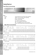
SD Advanced Appendix B Using the Keyboard/RC Interface Control To Control A Common Television Set To use the Keyboard/RC Interface Control as a common television remote handset, it is necessary to input a code specific to the relevant television. Below are detailed the procedures to follow and a listing of the codes associated with common television brands. How to Program The SD Advanced IR Remote Control 1. Turn the TV you wish to control ON. 2.
LG Panasonic Philips Pioneer Sanyo Sharp Sony Technics Toshiba 2021/2037/2045/2050/2210/2216/2239/2240/2267/2276/2280/2282/2298/2333/23 77/2397/2497/2502/2507/ 2517/2518/2521/ 2557/2563/ 2572/2577/2597/2609/261 5/2616/2622/2636/2646 2003/2009/2011/2037/2053 /2055/2059/2077/2084/2093/2094/2195/2200/2237 /2245/2261/2262/2263/2274/2287/2312/2330/2355/2356/2359/2364/2381/2389 /2451/2452/2492/2498/2527/2542/2580/2581/2582/2594/2596/2598/2600/2605/ 2608/2616/2645/2647/649 2042/2043/2044/2063/2074/2085/2086
SD Advanced Appendix C User Activity Logging User Activity logging can be enabled or disabled via the System Setting->Features menu. When this feature is enabled, the unit will record all actions performed via the user interface. These actions include Viewing the live stream, activating telemetry, altering the unit configuration, viewing recorded video, archiving video and any system events such as restarting the unit.
Locating the unit IP address using the serial port For guidance on locating the unit’s IP address via a serial port connection, please see below: 1. 2. 3. 4. With the mains power off, connect a standard 9DF-9DF RS232 communications cable from the PC to one of the serial port connections on the rear of the unit. On the PC, click Start->Programs->Accessories->Communications->Hyperterminal and create a new connection via the COM port using these settings.
SD Advanced Appendix E Configuring Your PC for the Videolan VLC Player The Multicast page allows recordings from the unit’s camera input to be forwarded to a port address. To utilise the Multicasting function (refer to Configuration Menu: Network Settings->Multicast SetUp for guidance). This system has been validated using the ‘Videolan VLC media player for MS Windows. The Videolan VLC media player can be downloaded free of charge from: www.videolan.org/vlc/download-windows.
Locating and Changing Username/Password Details for Third Party IP Cameras via an FTP Connection For guidance on locating and changing a third party IP camera’s username and password via an FTP connection; please see below: Firstly use your chosen File Transfer Protocol (FTP) client to connect to the unit. Refer to your FTP client’s supporting documentation for guidance on how to connect to the SD Advanced.
SD Advanced Appendix G Unit Specification LANGUAGES Currently: English, French, Italian, German, Spanish, Russian, Czech, Danish, Finnish, Norwegian, Swedish & Dutch. CAMERAS 8, 16 and 32 camera inputs available. Auto detection on power up. Looping BNC connectors are provided for each camera input on 8 and 16 input models Option to view Live or Replay all or selected cameras without affecting recording. MONITOR VIEWING Main monitor: Full screen, picture in picture, quad viewing and multiscreen.
TEXT SUPPORT Through the inclusion of Text Support, the SD Advanced can search captured transaction data for specific goods purchased, transaction numbers, credit card references, keywords etc. and jump straight to the associated video sequence. Till interfaces are available for a wide range of till systems. NETWORKING CAPABILITIES A standard Ethernet connection allows live and recorded viewing on a networked PC using DM’s NetVu ObserVer software.
SD Advanced 182 Index Accessing the Configuration Webpages....................... 19 Accessing the menus on a local monitor...................... 18 Accessing the menus on a PC web browser................ 18 Activate New Feature.................................................. 122 Activity Grid Menu....................................................... 160 Activity Search Menu.................................................. 158 Activity Setup.............................................................
Dedicated Micros ©2010 SD Advanced The Configuration pages can be displayed on a local monitor. . .............................................................. 18 Time and Date ............................................................. 34 Timeline Navigation..................................................... 151 To configure your PC to utilise VLC............................ 178 Unit Operation............................................................. 143 Unit Specification........................
Dedicated Micros Ltd. 1200 Daresbury Park, Daresbury, Cheshire, WA4 4HS, UK Dedicated Micros France 9-13 rue du Moulinet 75013 Paris, France Dedicated Micros Germany Hamtorstaße 9 41460 Neuss, Germany Dedicated Micros, Australia PTY.