Installation Guide
Contents Introduction........................................................................................................3 Features............................................................................................................4 Important Safeguards........................................................................................7 Installing the Unit...............................................................................................9 Installation.............................
What is the… High Definition NetVu Console ? Enabling customers to deploy an additional viewing & control station with minimal installation requirements, NetVu Console allows a traditional telemetry keyboard and monitor combination to be placed anywhere the customer requires with no need to retrain operators. All that is required is an IP connection and power.
Features The HD NetVu Console from Dedicated Micros is equipped with an array of valuable features designed to enhance the operator experience.
MAP Users can now navigate around their CCTV installation using a graphical map. Selecting the relevant camera from the map will instantly connect the user to that cameras image stream. With the ability to load bespoke map images and floor plans to reflect their installations, the Maps feature is ideal for quickly identifying camera locations around a site or CCTV network. Installation Guide NV1 Point&go provides the user with easy to use, fast, accurate telemetry control via an attached monitor.
Design of the manual For ease of use, this manual has three parts: 1. Installation Shows details of how to install the unit and connect external devices. 2. Configuration Shows details of the units menus. 3. Operation Shows quick reference details on how to control the unit.
Installation Guide NV1 Important Safeguards Read Instructions All the safety and operating instructions should be read before the unit is operated. Power Sources This unit should be operated only from the type of power source indicated on the manufacturer’s label. Servicing Do not attempt to service this unit yourself as opening or removing covers may expose you to dangerous voltage or other hazards. Refer all servicing to qualified service personnel.
Regulatory Notes and FCC and DOC Information (USA and Canadian Models Only) Warning: This equipment has been tested and found to comply with the limits for a Class A digital device, pursuant to part 15 of the FCC rules. These limits are designed to provide reasonable protection against harmful interference when the equipment is operated in a commercial environment.
Installation Guide NV1 Installing the Unit Before you start Check the contents of the box Remove all items from the packaging and check the items listed below are present: Note: • HD NetVu onsole • 24Vdc PSU • Mains cables • NetVu Console Keyboard • USB Mouse • Quick Start Guide • External Storage Setup Guide • Installation and Operation Guide (CD) If any of these items are missing, please contact Dedicated Micros Technical Support team.
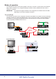
Network * SD Advanced SATA1 EXP KBD SERIAL 2 SERIAL 1 IR SERIAL 4 PTZ SERIAL 3 PTZ ALARMS I RELAYS O HDMI 1 OUT OUT IN IN A VID 17 VID 18 VID 19 VID 20 VID 21 VID 22 VID 23 VID 24 VID 25 VID 26 VID 27 VID 28 VID 29 VID 30 VID 31 VID 32 VID 1 VID 2 VID 3 VID 4 VID 5 VID 6 VID 7 VID 8 VID 9 VID 10 VID 11 VID 12 VID 13 VID 14 VID 15 VID 16 B AUDIO AUDIO NET USB MON MON A 16 cameras Modes of operation The HD NetVu Console can be set to operate in ‘Encode
Connect up to 4 analogue cameras to the BNC inputs labelled ‘CAM 1’ to ‘CAM 4’. If one or more of these cameras have PTZ control; RS485 telemetry can be utilised via a connection to the HD NetVu Console’s serial port. In place of an analogue cameras, a 3rd party IP camera can be connected to the Ethernet port labelled ‘NET1’ for recoding as a NetVu connected device. The ICR capability allows encoded cameras to be recorded to the HD NetVu Console’s SD card or to an AoE device.
DVR Mode The HD NetVu Console is also a fully fledged, enterprise class video server supporting analog and IP inputs. With embedded ICR (Integrated Camera Recording) Technology; the HD NetVu Console can make any analogue or IP camera into an edge-located recording device. Recording can be via a removable micro SD card, external USB drive or ATA over Ethernet (AoE) drive / RAID.
Installation Guide NV1 Installation Front Panel connections Data USB LEDs REMOTE SD 3x USB connector (2 normal / 1 micro size) Power Will illuminate when power is connected to the unit Status Will illuminate when the unit is active Infra-Red Input connector for IR Remote Control Extender Micro SD card port - available as storage for video footage in DVR and Encoder ICR modes.
Rear Panel connections Data SERIAL 1 NET 1 NET 0 /POE KBD Note: RS-232 / RS-485 / RS-422 (3 wire & 9 wire) RJ45 Ethernet network connector, 10/100 Mb/s Ethernet Network RJ45 Ethernet network connector, 10/100 Mb/s Ethernet Network / Power Over Ethernet : IEEE 802.3-2008. End span and bridging RJ12 connector for NetVu Console Keyboard The Serial 1 port and the keyboard connector utilise the same 485 bus which can provide either keyboard support or telemetry. Console mode uses to keyboard operation.
Installation Guide NV1 M4 Connecting the HD NetVu Console CA CA M CA Step 1 - Connecting a Monitor DIO AU CA M1 M3 USB 2 S TU STA R WE PO IN UT USC USB O IO D AU MI HD TE MO RE 1 NA MO Connect a local monitor either to the BNC output labelled ‘MON A’ output or the HDMI output. Note: Only one monitor connection is supported at any one time. The HDMI output will take precedence should monitors be connected to both monitor outputs.
Step 3 - Connecting to the Network R PW IN 1 L RIA SE T0 NE E PO T1 NE /R MS AR AL YS ELA D KB The HD NetVu Console supports two 10/100Mbps auto-detecting network port (operating on an internal switch). Use a CAT5 cable to connect the unit to the network. The unit also supports Power over Ethernet (PoE). This allows the power for unit to be supplied via the ethernet port. If the PoE function is to be utilised, connect the CAT5 cable to the network connector labelled ‘NET 0 POE’.
Locating the Unit’s IP address The unit is configured using on-board web pages. This can be done remotely once the unit has been installed in its chosen location. The IP address of the unit is required to access these pages. When the unit is connected to a DHCP network for the first time, its IP address is unlikely to be known without referring to the settings of the network switch or router it is connected to. DHCP works by assigning an IP address at initial connection to the network.
Step 4 - Connecting Power R PW IN L1 IA SER T0 NE E PO T1 NE /R MS AR AL Y ELA D KB I The HD NetVu Console can use either the external PSU (supplied) or POE. If POE is not being utilised, connect the supplied external PSU to the unit and then to the wall socket or to a fused spur connection. Check local regulations before installation. Some countries require an Alarm/Security device be connected to a fused spur and not a wall outlet socket.
R PW IN 1 IAL SER T0 NE E PO Installation Guide NV1 Optional 2 - Alarms / Relays T1 NE S LAY /RE S RM A AL D KB Alarms The unit supports 4 normally open/closed alarm inputs via the ALARMS/RELAY connector, or one Global keyswitch input with camera specific inputs configurable as entry/exit alarms.
Keyboard The NetVu Console Keyboard enables a high degree of control over connected cameras. Button LIVE PLAY Description Function Live/Play Puts the unit into Live mode. Display Button functionality for future development. High/Low Button functionality for future development. R/G/Y/B/P Activates the relevant softkey function, refer to ‘Using the NetVu Console’. Help Button functionality for future development. AUDIO Audio Button functionality for future development.
Pause Rewind Fast Forward Installation Guide NV1 Copy COPY Button functionality for future development. In Live mode – Freeze the current display window. In play mode – Pause video in playback. When in Live mode – put unit into reverse playback from current time. When in Play mode – start rewinding from the playback time. When in Rewind mode – increase speed of rewind. When in Pause – Step back one frame. When in Play or Rewind mode – start fast forwarding from the playback time.
AUTO PAN PATROL PATROL AUTO PAN OK MENU EXIT Iris Open / Iris Close Control of telemetry functions. Lamps Control of telemetry functions. Auto pan Control of telemetry functions. Patrol Control of telemetry functions. Direction arrow up Menu and on screen navigation button. Direction arrow down Menu and on screen navigation button. Direction arrow left Menu and on screen navigation button. Direction arrow right Menu and on screen navigation button.
The unit can be configured either on the local monitor or over the network using a PC with Internet Explorer or similar browser. Both have near identical menu interfaces. Accessing the menus on a local monitor The Viewer and Configuration menus can be displayed on a local monitor (connected to BNC Connector ‘Mon’ or the ‘HDMI’ port on the unit). The viewer menus will display the images from the video source connected to VID 1 on initial connection.
Main Menu The main menu will be displayed when first accessing the unit remotely. This menu allows access to the Configuration and Viewer menus. Select the Configuration menu tab to access the Configuration menus, for further guidance refer to ‘Navigating the Configuration Menus’. Select the Event Search tab to access the unit’s Event Search function, for further guidance refer to ‘Event Search’.
The menu tree provides access to the configuration menus. The configuration pages are navigated using the menu tree (displayed on the left of each page). Selecting one of the menu options will display the relevant page. Associated sub-menus will then be available. Installation Guide NV1 Navigating The Menus Relevant menus can also be accessed directly from other menu screens via the coloured softkey options shown at the base of each menu. The options available will depend on the menu being viewed.
Entering Alpha-Numeric Data via a Local Monitor Numeric or text data is entered using the on-screen Virtual Keyboard (Arrow Key Editor). To display the Virtual Keyboard, highlight the relevant text input box and double press the left button of the USB mouse. The Virtual Keyboard is displayed. Use the cursor to select a character. Select ‘Submit’ to enter details, select ‘Cancel’ to exit without entering any text. Note: Any USB Keyboard (not supplied) can be connected via one of the USB ports on the unit.
The menus under the System Settings heading allow the unit’s core settings to be viewed, changed and the system software upgraded. IMPORTANT: Not all menus will be available in both ‘Console’ and ‘Encoder’ mode. The mode of operation can be selected in the Features->System menu (System Settings ->Features->System). The Attributes option displays details about the unit including the IP address, unit serial number, MAC address and software version.
Attributes This menu shows the general information about the unit including the version of software installed, the unit’s serial number and the allocated DHCP IP address. Product Descriptor Serial Number PCB Serial Number Product Code Earliest Recording System Name Video Standard Number of Cameras Global PPS Video Storage Gbytes MAC Address IP Address Sub Net Gateway Details the product model. Identifies the serial number of the specific unit. Displays the unit PCB (Printed Circuit Board) serial number.
The above address information is split into two columns. Each column relates to either Network port 1 (Net 1) or Network port 2 (Net 2). Software (Red) Time/Date (Green) Accounts (Yellow) Network (Blue) Refresh (Purple) Select this option to display installed software information (see below). Select to open the System->Time and Date page. Select to open the Display->User Accounts page. Select to open the Network->Network page. Refreshes the information on the current page.
Unit Status This menu details information regarding the status of the unit, notably the total time the unit has been operating and the time since its last reset. Status log information can also be exported via the ‘Export Logs’ option to a USB device (for guidance on the Export Log function refer to ‘System Settings->Maintain’).
Note: Greyed menu option will be available if the mode is changed from Console to DVR or Encoder, they are not available in the Console configuration. They are included for reference only. This menu details information regarding the status of the unit’s alarm contacts, alarm zones and relay outputs. Installation Guide NV1 Alarm Status Alarm Contacts/Zones/Relay Outputs Alarm Contacts, Alarm Zones and Relay Outputs that are in an ‘active’ state are shown light green.
About These menu allows access to numerous system information pages and detail various system logs. Select the an icon to view the relevant pages. Note: Refer to Appendix C for further information on the ‘About’ menu pages. System Information Software Reference General Information Record Details Select to open the System menu. System information will be displayed, refer to System Settings->System for guidance on the information available. Select to open the Software Reference menu.
Capabilities UI Information Profile Record Tables Camera Overview IP Network Load Select to open the Camera Attributes menu. This menu provides detailed information on the type of camera i.e. analog or IP and for IP cameras, the supported resolution and capabilities. Select to open the Capabilities menu. This menu details the function capabilities of your unit. Select to open the UI (User Interface) menu. This menu details basic information regarding your unit. The java applet path is also shown.
Logs The log files stored in the camera can be accessed from this page. Selected logs are displayed on the page below.
Installation Guide NV1 Network Security Logs The log files stored in the camera can be accessed from this page. Selected logs are displayed on the page below.
Language This menu allows the system language to be set. Changing the System Language will effect all menu pages. If required, the language can also be changed for the current session only. System Language Select to change the system language setting. Reset (Red) Select to reset the unit. Note: The unit MUST be reset to implement system language changes. Session Language Choose Reset(Red) Refresh (Purple) Select to change the language settings for the current session only.
This menu allows the time and date to be set on the unit. Required timezone information can also be established and the unit time synchronised to that of the PC being used to view the webpages. Note: If power is lost to the unit, time/date settings will be lost. System Time Current Time Zone Time Zone The current system time and date is displayed. Displays the currently selected time zone settings. Select the relevant timezone offset from the accompanying drop down menu.
PC Time Sync Time (Blue) Reset (Red) Set Time (Green) System (Yellow) Sync Time (Blue) Refresh (Purple) Displays the system time of the PC currently being used to view the webpages. Use this button to synchronise the time of the unit to that of the PC being used to view the webpages. Select to cycle the power to the unit. When current time/date as been entered, select this button to implement changes. Select to open the System->Attributes page.
Installation Guide NV1 Serial Ports This menu allows configuration of the unit’s Serial ports. For installation information, refer to the optional stages in ‘Installing the Unit’. Note: The Serial 1 port and the keyboard connector utilise the same 485 bus which can provide either keyboard support or telemetry. NetVu Console defaults to keyboard operation. Important: Configuring the Serial Port for Telemetry will disable the NetVu Console keyboard.
Note: When a telemetry protocol is selected, these settings will default to pre-determined values and should not normally be altered. Protocol This is a drop down list of serial telemetry protocols supported by the unit. Refer to ‘Appendix G’ for a full list of supported telemetry protocols. Note: IMPORTANT: Before the serial port is set to telemetry, ‘Enable 485 telemetry’ must be set to ‘True’ via the Features menu (System Settings->Features).
Cam Setup (Red) Serial (Blue) Refresh (Purple) Installation Guide NV1 Fail Rep patterning. If a particular channel is not in use or the camera has failed, select ‘Not Connected’. Select this option to activate a Failure report in the event of camera connection failure (video loss). Select to open the Camera->Setup page Select to open the System->Serial page Refreshes the information on the current page.
Audio The Audio menu allows settings for the bi-directional audio channel to be edited. Audio can be recorded from line input. Challenge audio i.e. originating from an Operator using NetVu ObserVer at a Remote Video Receiving Centre (RVRC) can be recorded. Audio 1/2 Use the drop down box to assign an audio function to each input, ‘Local’ is Audio recorded from local inputs, ‘Challenge’ audio originates from an Operator using NetVu ObserVer at a Remote Video Receiving Centre (RVRC).
These menus enables the activation of numerous system features. Features are grouped within four sub-menus: System, Network, Video and Other. Changing the Operational Mode will remove any configuration information and apply the default factory settings for the selected mode. Note: Greyed menu option will be available if the mode is changed from Console to DVR or Encoder, they are not available in the Console configuration. They are included for reference only.
Note: When de-selected here, the ‘E-mail Reporting’ menu will no longer be displayed in the menu tree. Remote Reporting Select this option to activate the Remote Reporting function, refer to ‘Network->Remote Reporting’ for more information. Keyboard Enable (485 bus) Select to enable a connected RS485 Keyboard unit. Automatic FTP Download Select this option to enable automatic FTP downloads to upgrade the unit and/or the webpages, refer to ‘Network Settings-FTP Download’ for more information.
Note: Greyed menu option will be available if the mode is changed from Console to DVR or Encoder, they are not available in the Console configuration. They are included for reference only.
Video Detected Video Standard The unit automatically detects the video standard being used i.e. PAL/NTSC. Video Resolution (h x v) Edit the resolution settings. This will be the default display resolution when viewing the unit’s menu pages. Deinterlace Filter When Enabled, this option will improve the appearance of moving objects by applying a deinterlace mask that minimises the comb effect that can be visible when recording high motion scenes in 4CIF mode.
Select to open the System->Features->System page Select to open the System->Features->Network page Select to open the System->Features->Video page Select to open the System->Features->Other page Refreshes the information on the current page.
Other Note: Greyed menu option will be available if the mode is changed from Console to DVR or Encoder, they are not available in the Console configuration. They are included for reference only. Auto Update Web Variables Configures the unit to update all system variables required for an automatic upgrade without requiring confirmation. Do not check this box if you run a customised applet. Enable Event Search Select to enable the Event Search option.
This menu allows the unit to be reset and a software upgrade to be performed via an inserted CD-R/ DVD-R or a connected USB device. Current unit settings can also be saved for future use and previously saved settings restored. Installation Guide NV1 Maintain Configuration Default (Green) Select to return the unit to its factory default settings. Note: Selecting the Default button will cause the system to reboot.
Note: For the latest software upgrades, please refer to the Dedicated Micros website: www.dedicatedmicros.com Note: Selecting the Default button will cause the system to reboot. Save (Purple) Restore (Blue) Note: Select to save current unit settings to the selected media. Select to restore previously saved settings from the selected media. Selecting the Restore button will cause the system to reboot. To/From Export Logs To Server Set as ‘USB’. Set as ‘USB’.
Installation Guide NV1 PowerScript Mgmt This menu enables installed PowerScripts to be activated/deactivated on start-up. Use the tickbox(es) to select/deselect installed PowerScripts, then select Save (Green). A system reset will be required for the changes to take affect. Note: Changes this page will alter the ‘Default.C’ file. If you already have a custom PowerScript on your unit which uses Default.
USB Configuration Note: Greyed menu option will be available if the mode is changed from Console to DVR or Encoder, they are not available in the Console configuration. They are included for reference only. This page allows one of the USB sockets on the unit to be configured for use as an external storage output. A high capacity USB device could then be connected and used to store recorded video images.
Refresh (Purple) This button will remove the reference to the video stored on the USB devices, allowing them to be overwritten. It does NOT delete the data instantly. Refreshes the information on the current page. Utilising USB Memory 1. Navigate to System -> Video Storage. Installation Guide NV1 Clear Video (Red) The Video Storage Allocation table displays drives that are available for video recording.
3. Note: Allocate the formatted and mounted storage for video storage by clicking on the ‘Allocate’ button. Allocation takes between a few seconds and a few minutes, depending on the size of the drive, and the Feedback column will display information about the allocation process. The unit will require a Reset once allocation is complete. The unit application drive is protected, if it is allocated the unit will only remove the video folder. Formatting any other device will remove all data.
Installation Guide NV1 Note: The system displays a confirmation box to ensure the correct device has been selected. Click OK to confirm, then reboot the system. Once the power has cycled, the system will build the required PAR files ready for recording to commence, progress will be displayed in the Feedback column. There will be a pause before recording begins, dependant on the size of the USB device as video partitions are built.
Console Settings The menus under the Console Settings heading allow the unit’s Viewer display settings to be altered and User Account details to be viewed and changed. IMPORTANT: The Console Setting pages will only be available when the unit is operating in either ‘Console’ or ‘Server’ mode. The Systems page dictates which cameras and systems the HD NetVu Console will connect to, and controls how the video feeds will be displayed.
Installation Guide NV1 Systems The unit can be configured with up to 20 systems. A system is a collection of DVRs and cameras selected from those DVRs. Systems are not formally connected networks but a collection of DVRs viewable over an IP network. Each system provides access and control of up to 99 cameras at any one time. Each individual system can be selected from a drop down menu. Camera numbering is sequential within that system (up to the maximum 99 cameras per system).
Auto Fill Save (Purple) When the Server URL has been entered, select the ‘Auto Fill’ option to auto include the Server Name and ALL available cameras from that server. Select to save current unit settings to the selected media.
This menu gives an overview of all connected cameras and their home servers across all systems. The numbers allocated to each camera, both ‘locally’ within each System, and ‘remotely’ by their servers are displayed. The Configuration pages for each connected server can also be accessed (if access rights permit). Note: This page will only be available if accessing the Configuration menus remotely i.e. via an IP connection.
Remote Monitors This menu allows monitors not physically connected to the unit to view camera images received by the unit. The IP address of the server connected to the monitor (or video wall) is required. Cameras can then be selected via the remote monitor Up to 16 remote monitors (or video walls) can be configured. Enter the IP address of the server connected to the monitor. Save (Purple) Select to save current unit settings to the selected media.
This menu allows configuration of settings for the Viewer function. For more information regarding this feature refer to ‘Operating The Viewer’. Installation Guide NV1 Viewer Defaults Default settings can be configured for accessing the Viewer function via a local monitor and also remotely via a network connection (settings can be optimised for either a LAN or WAN connection).
Video Output mode Select the display output that best suits the viewing monitor. Typically PAL Default is most suited for a CRT monitor, PAL Reduced for a TFT monitor. Select from: PAL Default PAL Reduced HD Default HD 4x3 Note: It will be necessary to reboot the unit to implement any change to the Video Output Mode. The unit can be rebooted via the Reset (Red) option.
Installation Guide NV1 Display This menu allows configuration of monitor settings used when viewing camera images and text data. Main monitor text Background Colour Text Colour Sequence Dwell (secs) Sequence main on startup Softkey Timeout Numeric Input Timeout( s) Hide Mouse Cursor It is possible to select text to be displayed on the main monitor. The text displayed will include; time, date, mode of operation (Set, Unset or Override), camera number and camera title.
Enable custom segment setup Camera selection full screen Select All (Blue) Save (Purple) Select to activate the custom segment setup feature. When selected, a user can configure a Quad or Multiscreen layout via the Viewer menu. The configured layout can include any camera in any available segment. Select to auto switch to full screen mode any camera channel selected from ‘Multi’ display (selected via the Viewer feature). Select to add all available cameras to the Spot Monitor Sequence.
Installation Guide NV1 Maps This menu allows images to be imported and used as maps that can be displayed in the Viewer Menus. The map can then have hotspots added to allow quick navigation to individual cameras. An overview ‘System Selection Map’ can also be added to navigate between different systems.
Increment by If using the Decrement (Red) or Increment (Green) buttons, enter the size (in pixels) that the hotspot will increase/decrease. Decrement (Red) Select to reduce size of hotspot. Increment (Green) Select to increase size of hotspot. Hotspot X coord Use to position the centre of the hotspot along the X axis e.g. entering 20 would place the hotspot centre 20 pixels from the left edge of the map. Hotspot Y coord Use to position the centre of the hotspot along the Y axis e.g.
The Map Data menu allows Map Config data to be Imported/Exported. This enables map data to be saved and stored for future use, or used between multiple DV-IP Servers. Note: The Map Data menu will only be available when viewing the menu pages remotely i.e. via the webpages. Installation Guide NV1 Map Data To save map data, highlight and copy all text displayed in the Map Data text window, then save this data as a text file.
User Accounts The unit can protect configuration procedures by limiting access via usernames and passwords. Account Types The available account types for which users and passwords can be assigned privileges are: • Admin FTP Assigning username and password requirements for the Admin FTP function will limit access to the unit via an FTP connection.
• Remote Users Assigning Local Users access privileges will limit access to the Viewer pages for local users. When implemented, the local user will be prompted for a username and password before access to the Viewer pages (via the main menu) will be granted. Assigning Remote Users access privileges will limit access to the Viewer pages for remote users. When implemented, the remote user will be prompted for a username and password before access to the Viewer pages (via the main menu) will be granted.
Camera Settings Note: Greyed menu option will be available if the mode is changed from Console to DVR or Encoder, they are not available in the Console configuration. They are included for reference only. The Camera Settings menus allow configuration of cameras connected to the unit. The Camera Setup page allows the quick configuration of all connected local camera channels (with a dynamic preview available).
Note: Greyed menu option will be available if the mode is changed from Console to DVR or Encoder, they are not available in the Console configuration. They are included for reference only. This menu allows the configuration of active camera channels. IMPORTANT: Note: The menu options displayed will differ depending on the camera ‘Type’ and ‘IP Mode’ selected. Ideally any setup options available locally on the camera should first be used to best obtain a suitable image quality.
Type IMPORTANT: Fail Rep Telemetry Default to preset after X mins Note: The settings will default to ‘Colour’. If Monochrome cameras are used, select ‘Mono’. Selecting ‘Mono’ will remove colour patterning. Select’ ‘IP’ for an IP Camera. If a particular channel is not in use or the camera has failed, select ‘No Conn’. The menu options displayed will differ depending on the camera ‘Type’ selected here. Select this option to generate a Failure report in the event of camera connection failure.
Installation Guide NV1 IP Camera - For reference only If a NetVu Connected IP Source is selected IP Type IP Mode Select the type of NetVu Connected source the camera stream is originating from. Select from: ‘NetVu Server’ - i.e. DVIP Server, DVIP RT, SD, SD Advanced, EcoSense. ‘NetVu Gen 2’ - i.e. DS2, BX2. NetVu Camera’ - i.e. the CamVu 2000 from Dedicated Micros. ‘NetVu ANPR’ - i.e. the HyperSense ANPR camera from Dedicated Micros. Select the IP mode used to receive incoming IP data.
IMPORTANT: Note: Remote codec When selected, the unit will utilise the codec in the remote NetVu connected video server/ camera to allow change Multimode profiles and perform additional activities such as VMD and Activity Detection as if the codec was an integral part of the DVR. If ‘Remote codec’ is selected, the loading on the unit’s internal codecs will be reduced. The Remote codec option is only applicable for NetVu Connected cameras.
This page allows different lens de-warping techniques to be applied to connected cameras. The unit can de-warp Fish-eye and Depressive Fish-eye lenses to present a normal aspect image. Title Lens Type Pitch Ratio (H) Ratio (V) Ratio x100 Cam Setup (Red) Cam Overview (Green) Refresh (Purple) Installation Guide NV1 Camera Lens Configuration - For reference only Shows the allocated name of the video source. Allows selection of fisheye, depressive fisheye and normal lens types.
Camera Overview Note: Greyed menu option will be available if the mode is changed from Console to DVR or Encoder, they are not available in the Console configuration. They are included for reference only. This menu details the general settings assigned to each of the local camera channels. To edit the settings assigned to any of these cameras: Click on Local Camera Setup to edit the settings held in the SD Advanced. Click on ‘Setup’ to open the Setup menu on the connected video source.
Installation Guide NV1 IP Stream Inputs Note: Greyed menu option will be available if the mode is changed from Console to DVR or Encoder, they are not available in the Console configuration. They are included for reference only. The IP Streams menu allows the selection of High, Medium and Low resolution settings for video sources originating from a network based source i.e. IP Server. These streams are configured on the remote device.
IP Camera (Yellow) Schedule (Blue) Refresh (Purple) Select to open the IP Camera Configuration menu. Select to open the Schedule->Setup page Refreshes the information on the current page. IP Camera Configuration - For reference only Channel Select a camera channel for review and adjustment. Only those cameras designated as ‘IP’ in the Camera Setup menu will be available, (Camera->Setup). Mode Select the IP mode used to receive incoming IP data.
Note: Additional IP cameras (further to existing local camera channels) are remote codec only. Therefore any NetVu Connected cameras will be applied above local camera level. Installation Guide NV1 IMPORTANT: Remote codec When selected, the unit will utilise the codec in the remote NetVu connected video server/camera as if it was directly connected inside the DVR.
Unallocated Cams Note: Greyed menu option will be available if the mode is changed from Console to DVR or Encoder, they are not available in the Console configuration. They are included for reference only. Channels can be utilised by the BNC connections on the unit OR by the sockets on any connected Layer3 Enhanced CCTV Switch.
Note: Greyed menu option will be available if the mode is changed from Console to DVR or Encoder, they are not available in the Console configuration. They are included for reference only. The Record Settings menus allow configuration of the unit’s record functions. Record settings can be configured for normal operation, on alarm, by schedule and for set holiday and weekend periods. Selected video data can be saved and protected, refer to the individual menus for further details.
Default Note: Greyed menu option will be available if the mode is changed from Console to DVR or Encoder, they are not available in the Console configuration. They are included for reference only. The unit has a range of pre-defined configurations available. As standard the unit can record at 5pps MPEG4. Alternatively the unit can be configured for 1pps JPEG or for MultiMode operation (note that this will result in the record duration being determined by the time period the unit is in alarm).
Installation Guide NV1 Profile Record Note: Greyed menu option will be available if the mode is changed from Console to DVR or Encoder, they are not available in the Console configuration. They are included for reference only. It is possible to set the unit recording configuration based on specific priorities. The MultiMode recording feature offers the ability to set different recording rates, resolutions and compression formats across unset, set and override modes.
Unset/Set/Override Event Note: Shows the recording quality that will be used by the camera during an Alarm or Event. Note that Set and Override schedules will be used only when Timed Schedules are applied. For further details refer to the ‘Schedules’ section. Unset, Set and Override modes can be given more recognisable titles i.e. Day, Night, Weekend via the Schedule menu (Record Settings->Schedule). Comp PPS Select image compression format (MPEG, JPEG).
Installation Guide NV1 Advanced Record Menu View Switch to the Simple Profile Record menu. Note: When Advanced Record settings have been changed, it is not possible access the Simple Record menu until the newly configured Advanced Record settings have been applied. To do this, open the Record menu and select the ‘Save’ option. It will then be possible to return to the Profile Record menu and access Simple Record. Days Recording Displays the record duration possible using the current configuration.
Size PPS GOP Note: Note: If JPEG is selected, the figure entered here will be the size of the JPEG transmitted (in Kbytes). JPEG file sizes can be configured within the range of 5-45Kbytes. Select the number of pictures recorded per second. If using MPEG4 recording, select the number of images recorded within a GOP (Group of Pictures). A GOP consists of an I-Frame (keyframe) and following P frames. The GOP is also the rewind interval and stop interval for MPEG recording playback.
Note: Greyed menu option will be available if the mode is changed from Console to DVR or Encoder, they are not available in the Console configuration. They are included for reference only. This menu enables configuration of the pre trigger feature (for cameras recording JPEG mode only). When enabled, the pre-trigger feature will buffer and store alarm recording prior to an event trigger.
Protect Video Note: Greyed menu option will be available if the mode is changed from Console to DVR or Encoder, they are not available in the Console configuration. They are included for reference only. This menu allows the unit to automatically protect and retain recorded data. Previously saved data can also be unprotected. Enter a start and end time and select ‘Reload List’ . All saved video files from the chosen time period will be shown in the upper textbox.
Select None Select All Unprotect (Yellow) Unprot all (Red) Protect (Green) Unprotect (Yellow) Refresh (Purple) This will refresh the video list according to the selections made in the Start Time/Date and End Time/Date dialog boxes. This de-selects all the available video files. This selects all the available video files. Select this option to unprotect recorded video for the selected time period(s).
AoE Setup Note: Greyed menu option will be available if the mode is changed from Console to DVR or Encoder, they are not available in the Console configuration. They are included for reference only. This menu allows configuration of the units ATA over Ethernet (AoE) function. AoE is a network protocol designed for simple high-performance access of storage devices over Ethernet networks. Importantly the external storage device must be located on the same network as the unit.
FDISK Refresh (Purple) This button will remove failed or powered down devices that had previously been recognised and are no longer available. This button will format the whole device, erasing all data previously available on it and setting it up for video data storage. Refreshes the current page.
Schedule Note: Greyed menu option will be available if the mode is changed from Console to DVR or Encoder, they are not available in the Console configuration. They are included for reference only. This menu allows the Timer Function names to be configured. The Timer Function enables the unit to automatically be put into set/unset mode at specific times on specific days. This can help reduce unnecessary alarm triggers. The mode will be set by the DVR that the camera is connected to.
Installation Guide NV1 Setup Note: Greyed menu option will be available if the mode is changed from Console to DVR or Encoder, they are not available in the Console configuration. They are included for reference only. This menu allows the Schedule function to be configured. This enables the unit to automatically be put into set/unset mode at specific times on specific days. This can help reduce unnecessary alarm triggers.
Enable-N/O Enable-N/C Enable EOL Select if the Keyswitch is to be normally open (UNSET). Then choose a contact to be used in a specific zone as the Keyswitch. Select if the Keyswitch is to be normally closed (SET). Then choose a contact to be used in a specific zone as the Keyswitch. Select to configure the Keyswitch for EOL. The End Of Line (EOL) option enables the Keyswitch to detect any changes in the electronic input resistance.
Note: Greyed menu option will be available if the mode is changed from Console to DVR or Encoder, they are not available in the Console configuration. They are included for reference only. This menu allows a user to temporarily switch the unit’s system state into set/unset/override mode. The user will be required to enter their name and also the intended override duration. The action will be logged.
Refresh (Purple) Refreshes the information on the current page.
Note: Greyed menu option will be available if the mode is changed from Console to DVR or Encoder, they are not available in the Console configuration. They are included for reference only. This menu allows the unit to be automatically switched to Override mode for individual days i.e. public holidays or during a weekend (or any defined period). IMPORTANT: Holiday and Weekend settings cannot be entered when a Keyswitch has been enabled in the Record Settings->Schedule menu.
Alarm Settings Note: Greyed menu option will be available if the mode is changed from Console to DVR or Encoder, they are not available in the Console configuration. They are included for reference only. The Alarm Settings menus allow configuration of the unit’s alarm functionality. Individual alarm inputs and alarm zones can be configured. Global relays can be activated and the Activity grid set up. Refer to the individual menus for further details.
Installation Guide NV1 Inputs Note: Greyed menu option will be available if the mode is changed from Console to DVR or Encoder, they are not available in the Console configuration. They are included for reference only. This menu allows configuration of the alarm settings, refer to ‘Installing the Unit’ for hardware installation guidance. Number This identifies which input is being configured. The unit supports 4 on-board alarms. Enabled Each input must be enabled to function.
Pulse Ext (s) A pulse extension is used to prevent double triggers on a single alarm. The pulse extension time starts on an alarm trigger. If that contact is triggered again after the first alarm has finished but within the pulse extension, the second trigger will not restart the alarm, but will extend the current alarm duration. Enter the time in seconds for this extension. Nuisance This is a repetitive detector value.
Note: Greyed menu option will be available if the mode is changed from Console to DVR or Encoder, they are not available in the Console configuration. They are included for reference only. This menu allows the configuration of established alarm zones. A single or multiple trigger can be used to generate an alarm. It is possible to allocate up to 32 alarm zones to carry out a combination of actions. Use these options in conjunction with the Zone Actions menu.
Alarm Protect sec. This is the minimum time period in seconds (from the start of the alarm) that is protected from being overwritten. This time will include the alarm trigger, the pulse extension and any post alarm recording. It will not include pre-alarm images. Zone Input Rule This determines which input(s) will trigger the zone alarm: Input This sets an input or system function as the primary alarm trigger.
Select to open the Alarm->Activity menu Select to open the Alarm->Zone Actions menu Select to open the Alarm->Inputs menu Refreshes the information on the current page Installation Guide NV1 Activity (Green) Zone Act (Yellow) Alarm in (Blue) Refresh (Purple) 103 103
Zone Actions Note: Greyed menu option will be available if the mode is changed from Console to DVR or Encoder, they are not available in the Console configuration. They are included for reference only. This menu allows actions to be allocated to individual alarm zones; Primary and Secondary cameras can be allocated to the zone and actions undertaken following alarm activation. This page should be configured in conjunction with the Zone Inputs menu.
This must be enabled to allow the unit to send an alarm notification to an external destination i.e. an RVRC reporting via NetVu ObserVer. Archive Select to ensure the unit automatically downloads alarm images via an FTP connection to an FTP server. Add Still Image This will record a still image of the trigger along with the standard recording. This can then be sent on to an external destination.
Zone Actions Camera - For reference only Zone Primary Camera Secondary Cameras Zone Act (Yellow) Relays (Blue) Refresh (Purple) Select a zone (alarm) to configure. This allows a camera to be assigned as the primary camera associated with the Alarm Zone. The primary camera will be displayed when an alarm in this zone is triggered. This setting gives the facility to assign additional cameras to the zone.
Note: Greyed menu option will be available if the mode is changed from Console to DVR or Encoder, they are not available in the Console configuration. They are included for reference only. The unit has the capability to identify if a video input has been covered (by hand, spray paint, etc.) to prevent video images being viewed and recorded. The Camera Masking option identifies normal levels of contrast and uses them as a base line. It then compares these against a user defined minimum contrast level.
Contrast Create Database Entry Defines the contrast threshold the system uses to define that a camera is masked. Different cameras have different characteristics, it will be necessary to adjust this figure to avoid false alarms. Select to add an entry to the database following activation. This option is only available in Simple Activation. Zone Activation On Mask On Clear Defines the Zone trigger that will be activated when the view is masked.
Installation Guide NV1 Alarm Response Note: Greyed menu option will be available if the mode is changed from Console to DVR or Encoder, they are not available in the Console configuration. They are included for reference only. This menu enables response configuration following activity trigger on the camera channel. VMD Pulse Extension The pulse extension extends the trigger period to avoid double triggers of VMD occurring, i.e.
Profile Change Select to enable the unit to switch from Normal to Event recording following alarm activation. Alarm Reporting This must be enabled for the unit to automatically connect on alarm. Alarm 24hr This will ensure that Activity Detection is permanently enabled on this camera channel. Add Still Image This will record a still image of the trigger along with the standard recording. This can then be sent on to an external destination.
Note: Greyed menu option will be available if the mode is changed from Console to DVR or Encoder, they are not available in the Console configuration. They are included for reference only. The unit supports Activity Detection on all video inputs. It enables cameras to automatically detect any movement/changes within the video scene; this can trigger a number of operations such as FTP alarm notification and an increase in recording rate.
Grid Editor Reload Img (Red) Set All (Green) Clear All (Yellow) Use the Grid Editor by placing cells in areas of the camera view where movement will trigger an alarm. To enter cells navigate across the image via the Directional buttons of the I.R Remote Control). If viewing on a local monitor place a cell by pressing the OK button. If viewing via the webpages, use the mouse to navigate across the image, use the left mouse button to place a cell.
Installation Guide NV1 VMD Note: Greyed menu option will be available if the mode is changed from Console to DVR or Encoder, they are not available in the Console configuration. They are included for reference only. The unit supports VMD (Video Motion Detection) on all video inputs and allows cameras to automatically detect if there is any movement/changes within the video scene.
Mode Pixel Count (%) Pixel Change (%) Reload Image (Red) Clear All (Green) Default Grid (Yellow) The zone mode identifies when the reference image is taken for triggering VMD. The options are: Normal The reference image is updated approx every second. This will only allow small changes in the scene without triggering Last trigger The reference image is only updated when the VMD is triggered and is best used under controlled lighting, i.e. so there are no false triggers due to ambient light changes.
Installation Guide NV1 Global Actions Note: Greyed menu option will be available if the mode is changed from Console to DVR or Encoder, they are not available in the Console configuration. They are for reference only. This menu allows configuration of the default relay actions supported on the unit. The unit supports one onboard relay connection and global relay settings. This global relay can be triggered under specific conditions i.e. on receipt of any alarm or notification of Activity Detection.
Network Settings The Network Settings menus allow configuration of the unit’s network functionality. Key network settings can be established such as ‘fixing’ the unit’s IP address and maximum transmission rate. E-mail, remote reporting on alarm and FTP download can also be configured. Refer to the individual menus for further details. The Network Settings page allows configuration of the unit’s network connections such as the name assigned to the unit and its IP address.
Installation Guide NV1 Network Note: Greyed menu option will be available if the mode is changed from Console to DVR or Encoder, they are not available in the Console configuration. They are included for reference only. This menu allows additional network settings to be configured if required. Server Name IP Address Sub Net Gateway Primary DNS Max Transmission Rate Tx Image Buffers Ethernet MTU bytes Mx Transmission Timeout ms PPP Base IP This field can be edited to allocate a name to the unit.
PPP Idle Line Timeout s PPP Link Down Timer mins Hangup After Alarm Reset (Red) Rem Report (Green) E-Mail (Blue) Refresh (Purple) This is the time (in seconds) the unit will wait before disconnecting the PPP (Point to Point Protocol) link if data has not been transmitted or received. If for any reason the PPP connection is lost, this is the time (in minutes) before the unit will be forced to drop the PPP connection. Select to close the network connection following transmission of alarm data.
Installation Guide NV1 Live Transmissions Note: Greyed menu option will be available if the mode is changed from Console to DVR or Encoder, they are not available in the Console configuration. They are included for reference only. The unit transmits live images using JPEG or MPEG formats. The NetVu Connected remote viewing software will use the settings configured on this page as the defaults for JPEG & MPEG; High, Medium and Low settings.
Res For MPEG and JPEG transmission, select image resolution settings (4CIF, 2CIF, CIF or QCIF). Size_rate For JPEG, the figure entered will be the size of the JPEG transmitted (in Kbytes). For MPEG4 the figure will be the bit rate allocated. A higher rate will provide better quality picture display. JPEG file sizes can be configured in the range of 5-45Kbytes and MPEG bit rates in the range of 45-2500Kbits/second. PPS This shows the number of pictures transmitted per second.
Note: Greyed menu option will be available if the mode is changed from Console to DVR or Encoder, they are not available in the Console configuration. They are included for reference only. The Multicast page allows recordings from the unit’s camera input to be forwarded to a port address; enabling multiple viewers to view live data using a suitable media player without the need to directly connect to the unit.
Multicast Method Select the multicast forwarding method. Select from ‘SAP’ (to use session announcement protocol operation), ‘HTTP’ (to use cgi control operation) or ‘SAP+HTTP’ (both methods used simultaneously). Enable TTL (Time to Live) Tick this option to enable multicast. This option can be configured to limit which users can access the images.
Note: Greyed menu option will be available if the mode is changed from Console to DVR or Encoder, they are not available in the Console configuration. They are included for reference only. The unit can automatically transmit an email to an SMTP Server under numerous conditions i.e. on start up, on receipt of an alarm, camera failure etc. This allows the unit to be installed in unmanned applications where a Remote Video Response Centre (or Manager etc.
Sender E-mail Sender Display Name Send on Startup Send on Alarms Send on Camera Fail Send on Activity Event Send Image E-mail Image Res Log E-mail Test E-mail (Red) Zone Act (Green) Network (Yellow) Rem Reporting (Blue) Refresh (Purple) These optional fields indicate the source of the e-mail notification. If the fields are left blank the unit will use the system name to create a sender name. This is the sender name that will be shown in the e-mail name field. Select to send e-mail notification on startup.
Note: Greyed menu option will be available if the mode is changed from Console to DVR or Encoder, they are not available in the Console configuration. They are included for reference only. This menu details the configuration requirements for the unit to report to a Remote Video Receiving Centre (RVRC) following alarm activation. Note: This menu will only be displayed if ‘Remote Reporting’ is selected in the System Settings->Features menu.
Alarm Server ref. ID Remote Alarm Reporting Remote Cam Fail Reporting Remote Startup Reporting ARC Ping Enabled Alarm Responder Port Dial Retry Time (secs) Dial Count Zone Act (Green) Network (Yellow) E-mail (Blue) Refresh (Purple) This is the reference name/ID that will be presented to the RVRC viewing application. It should therefore have some significance to the Operator. This must be enabled for the unit to automatically connect on alarm.
Note: Greyed menu option will be available if the mode is changed from Console to DVR or Encoder, they are not available in the Console configuration. They are included for reference only. Any of the video inputs on the unit can be made available for transmission to a webserver via a designated webcam server. These images can then be incorporated into a web page and accessed via a standard web browser.
Password Update Interval Select Camera Input Webcam Enable Webcam Resolution If it is necessary to use an authentication process to access the webcam server, enter the relevant password here. This is the minimum update interval between each image transmitted from the unit. This allows individual video inputs to be enabled for upload to the webcam server. The Web Cam function can be: ‘Always Enabled’, ‘Enabled when system SET’, ‘Enabled when system UNSET’ or ‘Disabled’.
Note: Greyed menu option will be available if the mode is changed from Console to DVR or Encoder, they are not available in the Console configuration. They are included for reference only. The unit can archive images to a central FTP (File Transfer Protocol) server. This could be on receipt of an alarm, activation of the Activity Detection or at a scheduled time to backup recorded video.
Download options Select one of the following options from the drop down menu: On Connection This will automatically start the Archive download when the unit detects the archive destination is present. Scheduled It is possible to force the unit to archive images at a scheduled time, enter a time to activate this function each day.
Installation Guide NV1 Firewall This page allows configuration of the on-board firewall. The top ports are pre-configured with typical settings that can be edited, there are user defined ports available at the bottom of the list. Preconfigured ports can be disabled by unchecking the ‘open’ box. Enable PING response By default this option is enabled and allows the unit to be pinged.
Connections This page shows the IP addresses of users connected to this unit. It is for information only and cannot be edited or configured.
Note: Greyed menu option will be available if the mode is changed from Console to DVR or Encoder, they are not available in the Console configuration. They are included for reference only. The Features and Text menus allow activation of the units analytics and third party IP camera features plus configuration of the unit’s text in image and keywords functionality. Refer to the individual menus for further details.
Event Search Note: Greyed menu option will be available if the mode is changed from Console to DVR or Encoder, they are not available in the Console configuration. They are included for reference only. The Event Search menu allows recorded event images to be quickly searched for and reviewed. The Search criteria can be limited to a specific date/time and/or individual cameras.
After selecting ‘Search’ (Red), a still image of each captured event (within the chosen search criteria) will be displayed. It may be necessary to scroll through the results pages to view all events. If the number of events exceeds the events displayed per page (configured in Event/Page). Installation Guide NV1 Event Search Results Click on the thumbnail image to playback an event. That event will then playback in the window at the top of the menu.
Operating the Viewer Navigation is via a colour coded softkey system. The colour bar provides an intuitive approach to operator and installer use. The function of the keys will change according to whether the unit is in Live or Playback mode. Below and overleaf are described the available Viewer menu pages.
Installation Guide NV1 View Control The View Control page allows the connected video input to be displayed full screen Red Green Note: Blue Full Quad Show currently selected camera full screen. Displays four images on-screen, putting the currently selected camera in the top left segment of the four, and will increment all cameras by one if pressed again i.e. if cam 1 is shown top left, cam 2 top right etc. then the views will increment to cam 2 top left, cam 3 top right etc.
Video Control The Video Control page offers video playback functions i.e. play, pause, rewind and fast forward. Red Green Yellow Blue ll << > >> Purple Next Freezes current video display. Rewinds current video. Plays from current position. Fast forwards video up to current recording position. Opens the next page of the Viewer menu.
The Selection page allows access to various image and event playback functions. Red Green Yellow Blue IMPORTANT: Installation Guide NV1 Selection Page Play Switches the selected camera(s) shown on screen into Play mode. Goto Opens the GoTo menu. Event Displays the Events menu. Menu/Setup* Opens the Configuration menu pages. Selecting this option will exit the Viewer menus.
PTZ Program Option The Program page allows preset settings for PTZ cameras to be established and an ‘Origin’ base position established for a camera. Note: This page will not be available for all cameras. Red Preset Yellow Patrol Blue Purple Prog Next If Preset positions have been established for the PTZ camera, select the Preset option and enter a preset number. Refer to the ‘Presets’ menu page for further details on establishing preset positions.
Installation Guide NV1 Program Page The Program Menu page allows the PTZ configuration on the currently selected Telemetry camera to be accessed and configured (if such menus are available). Red Green Note: Yellow Blue Note: Purple Dome Store Select to display the Dome Menu page. Use to save the current view as a Preset for this camera. To re-send the camera to this position, select the camera, then press Next -> Preset -> (preset number).
Dome Menu Option The Dome Menu page allows camera specific menus imbedded on the currently viewed Telemetry camera to be accessed and configured (if such menus are available). Red Dome Menu Green Select Yellow Return Blue Menu Exit Purple Back Select to view camera specific sub-menus embedded on the Telemetry camera (if applicable). The camera specific menus will be overlaid across the screen. This option enables sub-menu content selection (dependent on the protocol selected).
Point&go enables an Oracle Dome camera to be controlled directly via the cursor. Select anywhere on the displayed image and the Oracle Dome camera will centre on that point i.e. to pan the camera to the right, click on the right hand side of the displayed image. The Oracle dome will pan and set the clicked point as the centre of the new image. Note: To use Point&go, PTZ mode must be selected (if available). Note: Oracle Dome cameras can also be controlled using the Keyboard joystick.
Timeline Navigation The Timeline Navigation page and the accompanying Video Timeline feature allows quick and easy investigation of recorded video data. The Goto button opens the initial Timeline Navigation page. Softkeys Note: The coloured softkey options will change depending on the scale used to review the recorded images. In the above example: • Selecting the 15 Mins (Red) button will change the softkey options to 15 minute segments i.e.
The Video Timeline allows intuitive, rapid navigation within recorded video. To aid navigation, the timeline can be set to display periods ranging from 15 seconds to four weeks. The timeline can be clicked anywhere in the scale to instantly play recorded images from that point. Date/Time Display (Grey) Shows the currently selected date/time. Note: The Date/Time Display shows the last time selected via the timeline.
Change Scale Utilise the buttons shown below to change the scale. Note: The coloured softkey buttons can also be used to alter the scale, refer to “Softkey Guidance” for further details). Decrease Scale button (Red) Decreases the scale of the displayed timeline by one step i.e. if the scale is currently one hour, selecting this button will reduce it to 15 minutes, selecting it again will reduce it to one minute etc. Increase Scale button (Blue) Increases the scale of the timeline by one step i.e.
Alarms and activity detection, plus system Events i.e. camera fails, are tagged and stored in the Event List. Each Event is labelled with an event type (alarm, activity or system) and its time and date. To view any additional pages of Event data, use the Yellow/Blue Softkeys Highlight a chosen event with the mouse to playback. Red Green Play Live Yellow Page - Blue Purple Page + Next Installation Guide NV1 Event List Select to playback the highlighted event.
Event Copy and Search Menu The Event Copy and Search menu allows events to be sent to the Copy menu via the Copy Option. All events currently held within the ‘Copy’ menu can be deleted via the ‘Clear All’ option. The ‘Filter option’ allows access to the ‘Filter Search’ menu. Red Green Note: Copy Select to add the currently highlighted event to the Copy menu. Clear All Select to clear ALL events from the copy menu. Single events can be deleted via the Copy menu.
When searching a large number of stored events, the Filter Search menu allows events to be filtered by time, camera channel and category. Installation Guide NV1 Filter Search Menu Filter Search Box From Time From Date Select a start time for the Event filter. Events prior to this time will be ignored. Select a start date for the Event filter. Events prior to this date will be ignored.
Cameras Text Type Red Blank Green Reset Yellow Now Blue Apply Purple Close Select which cameras are to be included within the Event search. A range of cameras can be selected by entering a hyphen between the first and last required camera i.e. 1-8. A selection of individual cameras can be chosen by entering a comma between each camera i.e. 1,3,5,8. Events captured by other cameras will be ignored. If searching for text in image events, enter the required text here.
The Activity Search menu allows the search criteria to be further narrowed to only include events which have occurred within specific segments of the camera view. Firstly, enter a start/end Time and Date, then select a camera channel. Use the Grid option to select a specific segment of the camera view. From Time From Date To Time To Date Cameras Installation Guide NV1 Activity Search Menu Select a start time for the Activity filter. Events prior to this time will be ignored.
Red Blank Green Reset Yellow Blue Grid Apply Purple Close Select to remove all data currently displayed in the Filter Search Box. Select to reset the Filter Search box. The current Time/Date will be displayed plus all available cameras. Select to open the Grid menu. Select to apply any change made to the Filter Search box. Select to return to the Event Copy and Search menu.
The Activity Grid menu allows the event search criteria to be further narrowed to only display events which have occurred within a segment of the camera view. A grid will be displayed across the camera image. Using the options outlined below, the grid can be configured to create activity zones within the image. Only events which have occurred within these zones will then be displayed in the Activity Search menu for the chosen camera channel.
IMPORTANT: Note: Purple The area (cells) highlighted yellow constitutes the activity detection zone. Any activity events occurring within the area created using the Start and End points will be ignored. Multiple zones can be created within the same camera view. Finish Select to return to the Activity Search menu.
Installation Guide NV1 Copy Menu Images and events can be copied to a USB Media for remote reviewing away from the unit (for evidential or monitoring purposes). The Copy Menu can be accessed via the ‘Archive’ (Yellow) button on the Archive Selection page. The Copy menu will display the Archive periods added to the Copy Event List. The Start and Finish date/times will be shown along with the estimated size of the download.
Appendix A - Pin-outs - For reference only Note: Greyed text refers to features that will be available if the mode is changed from Console to DVR or Encoder, they are not available in the Console configuration. They are included for reference only. Alarm & Serial Pin Outs Using Serial Ports It is possible to connect a variety of telemetry cameras to the unit, use the following table as a guide to the serial port connections.
User Activity Logging User Activity logging can be enabled or disabled via the System -> Features -> System menu. When this feature is enabled, the unit will record all actions performed via the user interface. These actions include Viewing the live stream, activating telemetry, altering the unit configuration, viewing recorded video, archiving video and any system events such as restarting the unit.
Appendix C - ‘About’ Pages The following pages detail the menus available via the ‘About’ configuration option (System->Status>About). General Information This page gives an overview of the units current settings including IP address, connections to the camera, the locations that data is being read from and written to, and which recording profile is active.
Note: Greyed menu option will be available if the mode is changed from Console to DVR or Encoder, they are not available in the Console configuration. They are included for reference only. This page displays the capabilities of a connected camera in terms of resolution and supported compression formats. This camera does not support audio, alarms, relay or lens de-warping so all these parameters return 0.
Capabilities This information page shows the capability settings for the camera. These parameters determine how the camera performs and what options are available on the web pages.
The UI page shows the settings stored in the camera which configure the user interface.
Camera Overview This page details the general settings assigned to each of the local camera channels. To edit the settings assigned to any of these cameras; Click on Local Camera Setup to edit the settings held in the SD Advanced; Click on ‘Setup’ to open the Setup menu on the connected video source. Unalloc (Green) Refresh (Purple) Select to open the Camera->Unallocated Cams page Refreshes the information on the current page.
This page illustrates the network traffic utilised by the unit. The page refreshes every second. Refresh (Purple) Installation Guide NV1 IP Network Load Refreshes the information on the current page.
Appendix D - IP Address via Serial For guidance on locating the unit’s IP address via a serial port connection, please see below: Locating the unit IP address using the serial port 1. With the mains power off, connect a standard 9DF-9DF RS232 communications cable from the PC to one of the serial port connections on the rear of the unit. 2. On the PC, click Start->Programs->Accessories->Communications->Hyperterminal and create a new connection via the COM port using these settings.
The Multicast page allows recordings from the unit’s camera input to be forwarded to a port address. To utilise the Multicasting function (refer to Configuration Menu: Network Settings->Multicast SetUp for guidance). This system has been validated using the ‘Videolan VLC media player for MS Windows. The Videolan VLC media player can be downloaded free of charge from: www.videolan.org/vlc/download-windows.
Appendix F - Monitor Output Open a File Transfer Protocol (FTP) client to connect to the unit, refer to the FTP client’s supporting documentation for guidance on how to connect to the unit. Note: The URL of the unit will be required before a connection can be made. No username/password is required for an FTP connection by default. If they have been assigned however, these must be entered before access will be allowed.
Installation Guide NV1 Appendix G - Unit Specification LANGUAGES Currently: English, French, Italian, German, Spanish, Russian, Czech, Danish, Finnish, Norwegian, Swedish & Dutch. HD NETVU CONSOLE DATA 2 port 10/100 Ethernet switch 4 analogue 75 Ohm video inputs 1 analogue 75 Ohm video output 1 HDMI output 3 USB ports 2 serial ports (sharing a single 9 way D connector) 1 keyboard port compatible with KBS1 and KBS2 1 port for IR remote control extender CAMERAS 4 analogue inputs. Auto detection on power up.
WEB PAGE CONFIGURATION Simple Web page configuration will allow the following functions to be configured: Unit setup, Manual update of viewing profiles, Network, Audio and Alarm settings BROWSER: IE 5.5 / Firefox 2.0 and above DEVELOPER: Java via Dedicated Micros SDK POWER SUPPLY: 12W External Power Supply POWER OVER ETHERNET IEEE 802.3af-2003 (12.95W). End span and bridging injectorssupported DIMENSIONS: 125 (L) including connectors x 58(H) x 130 (W) WEIGHT : 0.
Installation Guide NV1 Notes 169 169
Index About............................................................................. 32 Accessing & Configuring the Unit................................. 23 Accessing the Configuration Webpages....................... 23 Accessing the menus on a local monitor...................... 23 Accessing the menus on a PC web browser................ 23 Account List.................................................................. 69 Activity..........................................................................
With Keyswitch Disabled............................................... 94 Zone Actions............................................................... 104 Zone Actions Camera - For reference only................. 106 Zone Activation........................................................... 108 Zone Inputs................................................................. 101 Installation Guide NV1 Power............................................................................ 14 PowerScript Mgmt..........
Dedicated Micros Ltd. 1200 Daresbury Park, Daresbury, Cheshire, WA4 4HS, UK Dedicated Micros France 9-13 rue du Moulinet 75013 Paris, France Dedicated Micros Germany Hamtorstaße 9 41460 Neuss, Germany Dedicated Micros, Australia PTY.