
Operating Instructions and Installation Instructions


Dedicated Micros ©2010
9
CamVu 2000
DRAFT
Overview
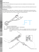
Step 1 - Mounting the Camera
Securely mount the camera to its bracket or housing via the 1/4-20 UNC threaded hole in its base. The
camera may be mounted inverted as the images can be electronically ‘tipped’ (see Conguring
the Unit->Camera)
IMPORTANT: To avoid damaging internal components, the screw must not project more than 15mm
inside the unit.
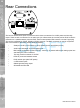
Step 2 - Connecting to the Network
Note: If the device utilises POE (Power Over Ethernet), this step should be postponed until all other
devices are connected, refer to ‘Power over Ethernet’ for details on available POE Injector.
The CamVu 2000 supports one RJ45 network port. Use a properly screened Ethernet cable to connect the
unit to the network.
By default the unit is congured for DHCP (Dynamic Host Conguration Protocol). DHCP works on assigning
an IP address at initial connection to the network. It is however possible for this IP address to change
without notication (i.e. in the case of power failure). Therefore it is recommended that the CamVu 2000 is
allocated a xed IP or DNS address to remove the possibility of address change.
Note: Refer to the section ‘Conguring the unit’ for information on nding and setting the IP address
5.13
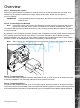
Step 3 - Connecting Video
The CamVu 2000 has a 75Ω BNC connector congurable for PAL or NTSC which can be used to focus the
lens during installation. The video feed is also sent via the network connection.
Step 4 - Connecting Alarms
The CamVu 2000 supports two EOL (End Of Line) alarm inputs, these are located on the push t connector.
The End Of Line (EOL) functionality is part of the Advanced Alarms supported on NetVu Connected products
and included features required for Central Monitoring and is compatible with the British Standard BS8418.