CamVu 2000 Installation and Operation Manual
CamVu 2000 Contents Introduction................................................................................................3 Rear Connections......................................................................................8 Overview....................................................................................................9 Configuring the Unit................................................................................. 11 System........................................................
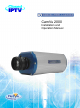
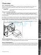
1.03 Offering up to six times the definition of analogue cameras, the Dedicated Micros CamVu 2000 Camera is ideal for situations where high resolution, high quality images are required.
CamVu 2000 • Minimum light requirement to produce a colour image approximately 0.15lux • Signal to noise better than 60dB • SD media slot • 2 x EOL alarm inputs • 500mA light duty relay output Benefits • The camera supports recording to local SD card or network attached storage using ATA over Ethernet • The latest technology provides low light performance superb image quality and colour fidelity in variable and high contrast lighting conditions.
EN 61000-6-3 EMC Standard Residential, Commercial and Light Industry. • EN 62000-3-3 Limitations of voltage changes, fluctuations and flicker in public low-voltage supply systems for equipment with rated current up to 16A. • EN 61000-3-2 Limits for harmonic current emissions for equipment with rated current up to 16A. • EN 50130-4 Immunity requirements for components of fire, intruder and social alarm systems. • EN 60950 Safety of IT and similar equipment. • EN 55022 Class A.
CamVu 2000 Power Sources This unit should be operated only from the type of power source indicated on the manufacturer’s label. Power over Ethernet The camera can be powered from any suitable PoE injector conforming to IEEE 802.3-2008. End span and bridging injectors supported. POE Injector The Dedicated Micros POE Injector is designed to enable the use of POE (Power over Ethernet) before a POE capable switch has been installed.
Layer 3 Enhanced Switch shown, normal Ethernet switch or DVR/ NVR connection also compatible. POE Injector Power Supply specification Adaptor socket - 5.5mm diameter with a 2.
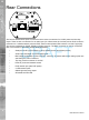
CamVu 2000 Rear Connections The CamVu 2000 features push fit connectors which house connections for 12VDC power and the relay output. There are also connections for an audio input (via 3.5mm stereo jack socket) and an RJ45 socket for connection to a suitable network point and POE. Serial communications with camera is via the D type plug. This can be configured for RS232, RS485 or RS422 protocols. The BNC connection is used in conjunction with a local monitor to focus the camera during installation.
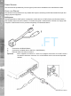
Step 1 - Mounting the Camera Securely mount the camera to its bracket or housing via the 1/4-20 UNC threaded hole in its base. The camera may be mounted inverted as the images can be electronically ‘tipped’ (see Configuring the Unit->Camera) IMPORTANT: CamVu 2000 Overview To avoid damaging internal components, the screw must not project more than 15mm inside the unit.
CamVu 2000 Step 5 - Connecting Audio The CamVu 2000 support a single channel of bi-directional audio, accessible through NetVu ObserVer. Connect the audio equipment to the 3.5mm stereo socket. The tip of the jack shall be used for audio input. The following modes of operation are supported: • Challenge – one way audio, DVR to camera, optionally recorded. • Listen – one way audio from the camera to the DVR, optionally recorded. • Help Point – two way audio, optionally recorded. 5.
Using the Unit with Secure Closed IPTV CamVu 2000 Configuring the Unit 1) Connect the camera to a Closed IP Network switch using Cat5 network cable. The POE version of this camera will work with the DM/NSW/CPP model switch. The non POE version of the switch works with the DM/NSW/CP model switch. The POE version will also work with DM/ NSW/CP model switch if connected to a POE injector and separate power supply.
CamVu 2000 Zero_conf configuration If a permanent IP address is not assigned to the unit, it will attempt to contact the DHCP server every time it starts up, and periodically thereafter. The unit support zero-configuration networking (sometimes known as Bonjour), this enables automatic discovery of computers, devices, and services on IP networks.
The menus under the System Settings heading allow the unit’s core settings to be viewed, changed and the system software upgraded. The System option displays details about the unit including the IP address, unit serial number, MAC address and software version. CamVu 2000 System The Status page displays information about the unit’s operating condition, shows how long the unit has been operating and the reason for the last reset. It also shows the camera status.
CamVu 2000 Attributes This menu shows the general information about the unit including the version of software installed, the unit’s serial number and the allocated DHCP IP address. draft Product Descriptor Serial Number PCB Serial Number Product Code Earliest Recording System Name MAC Address IP Address Sub Net Gateway 14 Number of Cameras Global PPS Details the product model. Identifies the serial number of the specific unit. Displays the PCB (Printed Circuit Board) serial number of the unit.
Highlights the available video storage capacity in Gigabytes. Displays the video standard adopted by the unit i.e. PAL, NTSC.
CamVu 2000 Software This page details the installed software and may be needed if calling Technical Support. draft System (Red) Diagnostics (Blue) Refresh (Purple) Links back to the System Setttings page Opens the Status->Diagnostics page.
Diagnostics This page provides quick links to the pages required to fault find. CamVu 2000 Status draft System Information Software Revisions General Information Record Details Camconfig Details Refresh (Purple) Opens the System Settings->System page. Opens the System Settings->Software page. Opens the General Information page (refer to ‘General Information’). Opens the Record Details page (refer to ‘Record Details’). Opens the Camconfig Details page (refer to ‘Camconfig Details’).
CamVu 2000 General Information draft Diagnostics (Blue) Refresh (Purple) Opens the Diagnostics page Refreshes the current page 18 Dedicated Micros ©2010
CamVu 2000 Record Details draft Diagnostics (Blue) Refresh (Purple) Opens the Diagnostics page Refreshes the current page 19 Dedicated Micros ©2010
CamVu 2000 Camconfig Details draft Diagnostics (Blue) Refresh (Purple) Opens the Diagnostics page Refreshes the current page 20 Dedicated Micros ©2010
This menu details information regarding the status of the unit, notably the total time the unit has been operating and the time since its last reset. CamVu 2000 Unit Status draft Time since last reset Total running time Reset code Restart reason Alarm Status(Yellow) Refresh (Purple) Details the time since the unit was last reset. Details the total time the unit has been operational. The last reset code used is displayed. The reason for the last restart is displayed i.e. Controlled User Reset.
CamVu 2000 Alarm Status This menu details information regarding the status of the unit’s alarm contacts, alarm zones and relay outputs. draft Alarm Contacts/Zones/Relay Outputs Alarm Contacts, Alarm Zones and Relay Outputs that are in an ‘active’ state are shown light green. ‘In-active’ ones appear dark green (not illuminated).
CamVu 2000 Language This menu allows the system language to be set. Changing the System Language will effect all menu pages. If required, the language can also be changed for the current session only. draft System Language Select to change the system language setting. Note: A server reboot will be required to implement system language changes. The unit can be rebooted via System Settings->Maintain->Reset. Session Language Select to change the language settings for the current session only.
CamVu 2000 Time and Date draft System Time Current Time Zone Time Zone 24 The current system time and date is displayed. Displays the currently selected time zone settings. Select the relevant timezone offset from the accompanying drop down menu. Date Format As default, the date is entered dd/mm/yy. It can also be displayed as mm/dd/yy or yy/mm/dd. Reset(Red) Resets the unit Time Format As default, the time displayed is in 12 hour format. This can be changed to 24 hour if required.
The PC Time and Sync Time options will only be available if viewing the menu via the webpages.
CamVu 2000 Serial Ports This menu allows configuration of the unit’s Serial port. draft Serial Port Port Config 26 These is one serial port available on the unit. The serial port can be configured for specific uses.
The Audio menu allows settings for the audio channel to be edited. Audio can be recorded via input. CamVu 2000 Audio draft Audio Recording This option allows the audio recording to be activated (Enabled) or deactivated (Disabled) Use The Audio output can be used for local playback, challenge, or disabled Record Gain This option allows the Record Gain level to be set. This is the base setting from which the AGC (Automatic Gain Control) will operate. Select from 1 to 15.
CamVu 2000 Features This menu enables the activation of system features such as Email Reporting. System (Red) Network (Green) Video (Yellow) Other (Blue) Refresh (Purple) Opens the System Features page Opens the System Features Network page (below) Opens the System Features Video page (below) Opens the System Features Other page (below) Refreshes the current page System Features draft User Logging Camera Masking Note: Remote Reporting Enable this option to activate User Logging.
When de-selected here, the ‘Remote Reporting’ menu will no longer be displayed in the menu tree. Webcam Support Select this option to activate the Webcam function. This allows the unit to emulate a webcam and send image from one video feed in webcam format, refer to ‘Network Settings->Web Cam’ for more information. Note: When de-selected here, the ‘Web Cam’ menu will no longer be displayed in the menu tree.
CamVu 2000 System Features Video draft Deinterlace Mask Disable Transcoding Partial Full Duplex Select this option to improve display clarity and minimise the comb effect that may be visible when recording high motion scenes. Transcoding reduces the size of images to be transmitted across a network whilst recording the original higher resolution image. This reduces network traffic but increases the overhead on the unit.
CamVu 2000 System Features Other draft Auto Update Web Variables This is used to enable/disable the weppage auto update acceptance option which is displayed when the webpage version has been updated. The default is to auto accept and update the webpages. Enable Event Search Page Select to enable the Event Search option. Note: When de-selected here, the ‘Event Search’ menu will no longer be displayed in the menu tree.
CamVu 2000 Maintain This menu allows the unit to be reset and a software upgrade to be performed via an inserted CD/DVD or a connected USB device. Current unit settings can also be saved for future use and previously saved settings restored. draft Server Reset (Red) Configuration Default (Green) Select to restart the unit. Select to return the unit to its factory default settings and restart.
This page enables you to select which PowerScripts are automatically run when the unit starts up. Use the tickboxes below to select which scripts you require and then click Save. Note: Note: You will need to restart your unit for the changes to take effect. Clicking Save will alter DEFAULT.C, if you already have a custom PowerScript on your unit which uses the DEFAULT.C file, please contact your regional Technical Support before using this page.
CamVu 2000 Display Display Settings allow default settings to be established for the Viewer menu. The viewer can be used to simulate local operation over the network, allowing locally stored images to be viewed. The Viewer Defaults page allows the Viewer menu settings to be configured. The User Accounts page helps protect configuration procedures by limiting access to specific users via accounts and passwords.
The units Viewer function allows remote users to simulate local operation over a network. This menu allows configuration of settings for the Viewer function, refer to ‘Operating The Viewer’ for more information regarding the Viewer. CamVu 2000 Viewer Defaults draft Default Image Format Default Image Req Applet Location Images from cameras can be displayed in either JPEG or MPEG format. Images displayed full screen in the Viewer menus can be shown in either High Medium or Low resolution.
CamVu 2000 Set Location Reset (Red) Refresh (Purple) Select the applet location. Choose from ‘Default location’ i.e. the applet installed on the unit; or the ‘Dedicated Micros website’ option i.e. the remote applet. This button will restart the unit.
The unit can protect configuration procedures by limiting access via usernames and passwords. By default, no usernames and passwords are configured for any account type. CamVu 2000 User Accounts draft Account Types The available account types for which users and passwords can be assigned privileges are: Admin FTP Assigning username and password requirements for the Admin FTP function will limit access to the unit via an FTP connection. ● Default username:none Default Password:none.
CamVu 2000 Serial Assigning username and password requirements for Serial connections will limit access via a Serial link. ● Default username:none Default Password:none. Menu Configuration Assigning WebPage Configuration privileges will limit access to the Configuration menus when viewed remotely. When implemented, the user will be prompted for a username and password before access to the Configuration menus (via the main menu) will be granted.
The Camera menu page allows configuration of the camera setup. Refer to the individual menus for further details. The Camera page allows the quick configuration the camera setup.
CamVu 2000 Camera Setup This menu allows the configuration of local camera settings for the unit. draft Camera Title Exposure Time Brightness Flip Video Mirror Video Collection Resolution Refresh (Purple) This title can be edited to allocate a name to the unit. This is displayed when the unit is accessed via NetVu ObserVer and is set when transmitting information to a Remote Video Response Centre (RVRC) Set the camera target exposure rate (select from 1/1 to 1/100 seconds).
CamVu 2000 ICR Settings The ICR Settings menus allow configuration of the unit’s record functions. Record settings can be configured for normal operation, on alarm, by schedule and for set holiday and weekend periods. Selected video data can be saved and protected. Refer to the individual menus for further details. The Default page allows the basic Recording settings to be edited. The Profile Record page allows the recording configuration to be based on specific priorities.
CamVu 2000 Default The unit has a range of pre-defined configurations available. As standard the unit can record at 5pps MPEG4 and at a selected number of days. Alternatively the unit can be configured for 2pps JPEG recording on each camera or for MultiMode operation (note that this will result in the record duration being determined by the time period the unit is in alarm). Note: This page is only relevant if images are being recorded to the camera.
It is possible to set the unit recording configuration based on specific priorities. The MultiMode recording feature offers the ability to set different recording rates, resolutions and compression formats across unset, set and override modes for each individual camera. By varying the quality, bit rate and file size of recorded images, the MultiMode function enables the recording capabilities of the unit to be greatly increased. Note: This page is only relevant if images are being recorded to the camera.
CamVu 2000 Unset/Set/Override Event Shows the recording quality that will be used by the camera during an Alarm or Event. Note that Set and Override schedules will be used only when Timed Schedules are applied. Refer to the ‘Schedules’ section for further details. Note: Unset, Set and Override modes may be renamed via Record Settings->Schedule. Comp Select image compression format (MPEG or JPEG). PPS The accompanying dropdown list allows the number of frames captured per second to be set.
CamVu 2000 Advanced Record draft Menu View Switch to the Simple Profile Record menu. Note: When Advanced Record settings have been changed, it is not possible access the Simple Record menu until the newly configured Advanced Record settings have been applied. To do this, open the Record menu and select the ‘Save’ option. It will then be possible to return to the Profile Record menu and access Simple Record. Days Recording Displays the record duration possible using the current configuration.
CamVu 2000 Size PPS GOP Refresh (Purple) If JPEG is selected, the figure entered here will be the size of the JPEG transmitted (in Kbytes). JPEG file sizes can be configured within the range of 5-45Kbytes. Select the number of pictures recorded per second. If using MPEG4 recording, select the number of images recorded within a GOP (Group of Pictures). A GOP consists of an I-Frame (keyframe) and following P frames. Refreshes the current page.
This menu allows the Timer Function names to be configured. The Timer Function enables the unit to automatically be put into set/unset mode at specific times on specific days. This can help reduce unnecessary alarm triggers. The mode will be set by the DVR that the camera is connected to. When the unit is in Set or Unset mode, combine with different recording qualities and rates under normal and alarm conditions for a high degree of control in a range of situations.
CamVu 2000 RVRC This menu allows a user to temporarily switch the unit’s system state into set/unset/override mode. The user will be required to enter their name and also the intended override duration. The action will be logged. Note: Refer to the Schedule menu for details of how to configure Set, Unset and Override modes: Record Settings->Schedule. draft Current System Time 48 The unit’s current date and time information will be displayed. This will be logged with any override action.
This menu allows the unit to automatically protect and retain recorded data in the camera. Previously saved data can also be unprotected. Enter a start and end time and select ‘Reload List’ . All saved video files from the chosen time period will be shown in the upper textbox. These recorded ‘PAR’ files can then be selected and protected via their accompanying checkboxes and the Protect option. Selected video files can also be unprotected via the Unprotect option.
CamVu 2000 List From Date/Time List To Date/Time Refresh (Purple) This dialog box allows a search to be made within the protected video list starting from a specific Time and Date. This dialog box allows a search within the protected video list to conclude at a specific Time and Date. Refreshes the current page.
This menu allows configuration of the units ATA over Ethernet (AoE) function. AoE is a network protocol designed for simple high-performance access of storage devices over Ethernet networks. Importantly the external storage device must be located on the same network as the unit. AoE does not rely on network layers such as IP and TCP, making it non routable i.e. routers cannot be used to forward a packet across disparate networks.
CamVu 2000 Alarm The Alarm Settings menus allow configuration of the unit’s alarm functionality. Individual alarm inputs and alarm zones can be configured. Global relays can be activated and the Activity grid set up. Refer to the individual menus for further details. The Inputs page allows configuration of alarm channels. Two alarm channels are available. The Zone Input page enables the configuration of alarm zones. Up to 32 separate alarm zones can be created.
This menu allows configuration of the alarm settings, refer to ‘Installing the Unit’ for hardware installation guidance. CamVu 2000 Inputs draft Number This identifies which input is being configured. The unit supports 2 on-board alarms. Enabled Each input must be enabled to function. If the input is not enabled and an alarm is received, the unit will not acknowledge the alarm. N_O (Normally Open Contact) N_O indicates the non-alarm state of the input.
CamVu 2000 Nuisance Stuck Time (min) Reset (Red) Relays (Green) Status (Yellow) Zone In (Blue) Refresh (Purple) This is a repetitive detector value. When an alarm is received on the unit, it will store the alarm time and monitor the number of times the same detector is triggered within an hour period. If the detector is triggered the number of times entered here, the unit will deactivate this detector from triggering an alarm for an hour.
This menu allows the configuration of established alarm zones. A single or multiple trigger can be used to generate an alarm. It is possible to allocate up to 32 alarm zones to carry out a combination of actions. Use these options in conjunction with the Zone Actions menu. CamVu 2000 Zone Inputs draft Entry timer Exit timer Zone Title Pre-Alarm sec This is the number of seconds allowed for the user to enter the zone and disable the alarms.
CamVu 2000 Note: It is recommended that the Pre-Alarm option be set to the same value as the Pre-Trigger setting in the “Profile Record“ menu. This will ensure successful playback of high quality Pre-Trigger images. High quality pre-trigger images will only playback properly if review (playback) starts prior to the pre-trigger initiation. Alarm Protect sec This is the minimum time period in seconds (from the start of the alarm) that is protected from being overwritten.
This menu allows actions to be allocated to individual alarm zones. This page should be configured in conjunction with the Zone Inputs menu. CamVu 2000 Zone Actions draft Zone Primary Camera Alarm Colour Create Database Entry Profile Change Archive Alarm Reporting Email Image Add Still Image Dedicated Micros ©2010 Select a zone (alarm) to configure. This allows the camera to be assigned as the primary camera associated with the Alarm Zone.
CamVu 2000 VMD/Activity Inhibit Protect Alarm Images Email Reporting Relay Relay Duration Cam Options (Yellow) Rem Report (Red) Email(Green) Relays (Blue) Refresh (Purple) Select to inhibit (ignore) the VMD/Activity detection feature. Refer to ‘Activity Setup’ for more information. Alarm images can automatically be protected from being overwritten. The unit can send an email when an alarm is detected, refer to ‘Network-E-mail’ for more information.
This page allows camera masking to be configured. The Camera can detect when the lens has been obscured, ie by being covered or painted over. This page will enabled detection and set the threshold for activation.
CamVu 2000 Zone Activation draft Camera On Dwell Threshold Contrast On Mask On Clear Refresh (Purple) Shows the camera being configured Allows the features to be enabled/disabled Sets the time in seconds before the alarm is generated Sets the level at which the alarm is generated This setting is not adjustable Defines which zone will be activated when the camera is masked. Defines which zone will be activated when the camera is unmasked. Refreshes the current page.
The unit can be set up to detect either VMD or Activity, depending on the level of detection required. Video Motion Detection enables a greater degree of control over detection settings and configuration than the Activity Setup function. CamVu 2000 VMD/Act Response Setup draft VMD Pulse Ext (s) A pulse extension is used to prevent double triggers on a single alarm. The pulse extension time starts on an alarm trigger.
CamVu 2000 Profile Change Select to enable the unit to switch from Normal to Event recording following alarm activation. Alarm Reporting This must be enabled for the unit to automatically connect on alarm. Alarm 24Hr This will ensure that Activity Detection is permanently enabled on this camera channel. Add Still Image This will record a still image of the trigger along with the standard recording. This can then be sent on to an external destination.
The unit supports Activity Detection on all video inputs. It enables the camera to automatically detect any movement/changes within the video scene; this can trigger a number of operations such as FTP alarm notification and an increase in recording rate. A still image of the selected camera will be shown in the Grid Editor screen. To establish an Activity zone, edit the cells displayed across the image. This option should be used in conjunction with the Zone Inputs and Zone Actions menus.
CamVu 2000 Global Activity Mode Activity Channel Edit Action Activity Sensitivity Grid Editor Three options are available for Activity activation). Selecting ‘Active while at Preset 1’ will result in Activity mode functioning only when the camera is at preset position 1. Select ‘Active while camera not in motion’ for Activity mode to function only when the camera is still. Select ‘Always Active’ for Activity mode to be in constant operation.
The unit supports VMD (Video Motion Detection) to automatically detect if there is any movement/changes within the video scene. Note: Video Motion Detection enables a greater degree of control over detection settings and configuration than the Activity Setup function. Each of the 16 VMD Zones can be directly sized and configured to suit specific requirements. VMD can only be accessed and configured remotely via the webpages.
CamVu 2000 Camera Zone Displays the available Camera source. There are 16 VMD zones within the image that can be individually configured, select the zone from the drop down list. A selected zone can be re-sized by clicking the mouse button (use the USB mouse if viewing on a local monitor) and then moving and clicking the mouse again. A rectangle will then be displayed based on these two selected points. The zone mode identifies when the reference image is taken for triggering VMD.
CamVu 2000 Global Actions This menu details how to configure the default relay actions supported on the unit. The unit supports two onboard relay connections and global relay settings. These global relays can be triggered under specific conditions i.e. on receipt of any alarm or any notification of Activity Detection.
CamVu 2000 Network The Network Settings menus allow configuration of the unit’s network functionality. Key network settings can be established such as ‘fixing’ the unit’s IP address and maximum transmission rate. E-mail, remote reporting on alarm and FTP download can also be configured. Refer to the individual menus for further details. The Network page allows configuration of the unit’s network connections such as the name assigned to the unit and its IP address.
This menu allows network settings to be configured if required. The unit is DNS compliant, and can be referenced on the network using the configured server name (or serial number) if a DNS server is available . CamVu 2000 Network draft Server Name This field can be edited to allocate a name to the unit. This would be used if accessing the unit via a Domain Name Server (DNS).It will initially default to the serial number of the unit. IP Address An IP address can be manually allocated to the unit.
CamVu 2000 Max Transmission Rate kbits/sec This shows the maximum transmission speed for the network type being used. If set to ‘0’, transmission speed is not limited in the camera. Note: This setting will limit and override any higher transmission rate entered in the Video Transmission menu (Configuration menu->Live Trans). Force 10BaseT operation The unit supports 10 or 100BaseT half duplex transmission. Selecting this option will force the unit to operate at a 10BaseT connection.
The unit transmits live images using JPEG or MPEG formats. The NetVu Connected remote viewing software will use the settings configured on this page as the defaults for JPEG & MPEG; High, Medium and Low settings. CamVu 2000 Live Trans draft Filter By Megapixel High LAN/Medium WAN/Low VLBR This shows the transmission settings configured for a High quality LAN (Local Area Network) connection, Medium quality WAN (Wide Area Network) connection or a Low quality VLBR (Very Low Bit Rate connection).
CamVu 2000 PPS MPEG Type & Quality Refresh (Purple) This shows the number of pictures transmitted per second. For JPEG, the actual images transmitted will depend on the bandwith of the link, increasing the pictures sent per millisecond may introduce time lag if bandwith is not sufficient i.e. this forces the same quality image through the available connection. On MPEG transmission, increasing the pictures sent will also reduce the quality of the images i.e.
The Multicast page allows recordings from the unit’s camera input to be forwarded to a port address; enabling multiple viewers to view live data using a suitable media player without the need to directly connect to the unit. In multi viewing scenarios, the demands on the unit are significantly reduced; improving overall performance. This system has been validated using the ‘Videolan VLC media player for MS Windows. The Videolan VLC media player can be downloaded free of charge from: www.videolan.
CamVu 2000 Multicast Method Select from ‘SAP’, ‘HTTP’, ‘SAP + HTTP’ or ‘Always On’. SAP is recommended. SAP will advertise your stream over the network when using the UDP streaming method, using the SAP protocol, using the Multicast Address as the name of the stream. HTTP will stream by using the HTTP protocol on all the network interfaces of the server on port 8080. Enable Tick this option to enable multicast.
up, on receipt of an alarm, camera failure etc. This allows the unit to be installed in unmanned applications where a Remote Video Response Centre (or Manager etc.) would be notified by e-mail if any of these conditions occur. CamVu 2000 E Mail The unit can automatically transmit an e-mail to an SMTP Server under numerous conditions i.e.
CamVu 2000 Sender Email Sender Display Name Send on Startup Send on Alarms Send on Camera Fail Send on Activity Event Send Image Email Image Res Log Email Zone Act (Green) Network (Yellow) Rem Report (Blue) Refresh (Purple) These optional fields indicate the source of the e-mail notification. If the fields are left blank the unit will use the system name to create a sender name. This is the sender name that will be shown in the email name field. Select to send email notification on startup.
This menu details the configuration requirements for the unit to report to a Remote Video Receiving Centre (RVRC) following alarm activation. Note: This menu will only be displayed if ‘Remote Reporting’ is selected in the System Settings->Features menu. CamVu 2000 Remote Reporting draft Primary hostname Primary dial profile Secondary hostname Secondary dial profile Public (NAT) address This is the IP address or URL of the initial host that the unit will transmit an alarm message to.
CamVu 2000 Video server port Alarm server ref. ID Remote alarm reporting Remote camfail reporting Remote Startup Reporting ARC Ping Enabled Alarm responder port Dial retry time (secs) Dial count This field allows the RVRC to connect to the unit through a router that is using port forwarding e.g. if the video server does not appear on port 80 (HTTP), to the external network. Enter the port number used for forwarding here if required.
webcam server. These images can then be incorporated into a web page and accessed via a standard web browser. Note: This menu will only be displayed if ‘Webcam Support’ is selected in the System Settings->Features menu.
CamVu 2000 Select Camera Input Webcam Enable Webcam Resolution Network (Blue) Refresh (Purple) This allows individual video inputs to be enabled for uploading to the webcam server. The Web Cam function can be: ‘Always Enabled’, ‘Enabled when system SET’, ‘Enabled when system UNSET’ or ‘Disabled’. Select a High, Medium or Low webcam resolution settings to best match the monitor settings of the operator receiving the images. Opens the Network Settings -> Network page.
This page allows configuration of the onboard firewall. CamVu 2000 Firewall draft Enable PING response Table Entry Open TCP ports Open UDP ports Refresh (Purple) By default this option is enabled and allows the unit to be pinged. Disabling this option will make the unit less visible on the network Up to 32 Configuration settings may be entered. This list identifies the TCP ports that are on the system and available.
CamVu 2000 Connections This page shows the IP addresses of users connected to this unit. It is for information only and cannot be edited or configured.
The Analytics and Text menus allow configuration of the unit’s text in image and keywords functionality. Refer to the individual menus for further details. CamVu 2000 Features & Text The unit is AnalyticsCapable. Please call Dedicated Micros on + 44 (0) 845 600 9500 for further information on our range of Analytics based solutions. The Text In Image page allows the unit to integrate text data with recorded images i.e. a cash register with a camera positioned at the point of sale.
CamVu 2000 Features Dedicated Micros has created a range of analytics components and solutions designed to work with AnalyticsCapable products. The range of applications include: Automatic Number Plate Recognition (ANPR), Object Left and Removed, Access Control, People Counting and Perimeter Protection.
It is possible to integrate the unit into a system were text information can be stored with relevant images for review. This would be most useful in a Retail or Finance application were text data originating from a cash register could be displayed in real time with the video images of the same Point of Sale. Note: This menu will only be displayed if ‘Text in Image’ is selected in the System Settings->Features menu.
CamVu 2000 Text Filter Line length Number Visible Lines Background Colour Text Colour Enable Keywords Keywords pulse extension Select the text filter option from the drop down list. The options are: Plain Text (default), RAW, EPSON, Laserjet, DM POS Receipt, DM POS Journal, TVC-1066 This identifies the length of the lines that will be stored with the image. The default setting is 20 characters i.e. typically full screen. Controls how many lines of text are visible on screen.
This menu allows a specific keyword received via the text stream to be configured and enabled as an event trigger. The ‘Enable Keyword’ function needs to be activated in the ‘Text in Image’ menu for this feature to operate. CamVu 2000 Keywords draft Text Keyword The unit can be configured to react to a keyword appearing in text data and treat them as alarm zone inputs. In turn this generates events in the event database. . The keyword can be up to 20 characters in length.
CamVu 2000 Diagnostics The Diagnostics menus gives engineers the ability to quickly and accurately diagnose any problems with the unit. This menu will normally only be used on a Technical Support call. The Debug Parser menus allow detailed analysis of the debug output from the camera and maybe used to assist with fault finding. The debug can be filtered in order to isolate and highlight events that are of interest.
This menu allow detailed analysis of the debug output from the camera and maybe used to assist with fault finding. The debug can be filtered in order to isolate and highlight events that are of interest. CamVu 2000 Debug Parser draft View Filter Search text Text colour Background colour Font family Font size Font weight Refresh (Purple) Defines whether the debug settings on the debug output will be displayed. Specifiies which of the Debug Filters is being configured.
CamVu 2000 Event Search The Event Search menu allows recorded event images to be quickly searched for and reviewed. The Search criteria can be limited to a specific date/time on the camera. Note: Event Search will only be available when the ‘Enable Event Search Page’ option is enabled via the System Settings->Features menu. draft Event/Page Start Date Start Time End Date End Time Cameras Search (Red) Select the amount of event still images (thumbnail size) to be displayed per results page.
After selecting ‘Search’ (Red), a still image of each captured event (within the chosen search criteria) will be displayed. It may be necessary to scroll through the results pages to view all events. If the number of events exceeds the events displayed per page (configured in Event/Page). CamVu 2000 Event Search Results draft Click on the thumbnail image to playback an event. That event will then playback in the window at the top of the menu.
CamVu 2000 Unit Operation The unit can be viewed and accessed remotely via the webpages and the ‘Viewer’ menu option. Operating the Viewer Navigation is via a colour coded softkey system. The coloured menu provides an intuitive approach to operator and installer use. The function of the keys will change according to whether the unit is in Live or Playback mode.
The View Control page allows connected video inputs to be displayed full screen or in Quad/Multi way display format. The Help Video page can also be accessed. CamVu 2000 View Control draft Red Full Show currently selected camera full screen. Purple Next Opens the next page of the Viewer menu. Note: For information on creating Camera Selection maps. Refer to the Display Setting->Map Config’ section for further information.
CamVu 2000 Video Control The Video Control page offers video playback functions i.e. play, pause, rewind and fast forward. draft Red Green Yellow Blue Purple ll Freezes current video display. << Rewinds current video. > Plays from current position. >> Fast forwards video up to current recording position. Next Opens the next page of the Viewer menu.
The Selection page allows access to various image and event playback functions. CamVu 2000 Selection Page draft Red Green Yellow Blue IMPORTANT: Purple Play Switches the selected camera(s) shown onscreen into Play mode. Goto Opens the Goto menu. Event Displays the Events menu. Setup Opens the Configuration menu pages. Selecting this option will exit the Viewer menus.
CamVu 2000 Goto Menu Timeline Navigation The Timeline Navigation page and the accompanying Video Timeline feature allows quick and easy investigation of recorded video data. The Goto button opens the initial Timeline Navigation page. draft Softkeys The coloured softkey options will change depending on the scale used to review the recorded images. In the above example: • Selecting the 15 Mins (Red) button will change the softkey options to 15 minute segments i.e.
The Video Timeline allows intuitive, rapid navigation within recorded video. To aid navigation, the timeline can be set to display periods ranging from 15 seconds to four weeks. The timeline can be clicked anywhere in the scale to instantly play recorded images from that point. CamVu 2000 Video Timeline Date/Time Display (Grey) Shows the currently selected date/time. Note: The Date/Time Display shows the last time selected via the timeline.
CamVu 2000 Change Scale Utilise the buttons shown below to change the scale. Note: The coloured softkey buttons can also be used to alter the scale, refer to “Softkey Guidance” for further details). Decrease Scale button (Red) Increase Scale button (Blue) Left Navigation Arrow (Green) Decreases the scale of the displayed timeline by one step i.e. if the scale is currently one hour, selecting this button will reduce it to 15 minutes, selecting it again will reduce it to one minute etc.
Alarms and activity detection, plus system Events i.e. camera fails, are tagged and stored in the Event List. Each Event is labelled with an event type (alarm, activity or system) and its time and date. To view any additional pages of Event data, use the Yellow/Blue Softkeys. Selecting any Event with the mouse will display the full Event list. Highlight a chosen event with the mouse to playback.
CamVu 2000 Event Copy and Search Menu The Event Copy and Search menu allows events to be sent to the Copy menu via the Copy Option. All events currently held within the ‘Copy’ menu can be deleted via the ‘Clear All’ option. The ‘Filter option’ allows access to the ‘Filter Search’ menu. draft Red 100 Copy Select to add the currently highlighted event to the Copy menu. Green Clear All Select to clear ALL events from the copy menu. Note: Single events can be deleted via the Copy menu.
When searching a large number of stored events, the Filter Search menu allows events to be filtered by time, camera channel and category.
CamVu 2000 From Time From Date Cameras Text Type Red Green Yellow Blue Purple Blank Select a start time for the Event filter. Events prior to this time will be ignored. Select a start date for the Event filter. Events prior to this date will be ignored. Select which cameras are to be included within the Event search. A range of cameras can be selected by entering a hyphen between the first and last required camera i.e.1-8.
CamVu 2000 Activity Search Menu The Activity Search menu allows the search criteria to be further narrowed to only include events which have occured within specific segments of the camera view. Firstly, enter a start/end Time and Date, then select a camera channel. Use the Grid option to select a specific segment of the camera view. draft From Time From Date To Time To Date Select a start time for the Activity filter. Events prior to this time will be ignored.
CamVu 2000 Cameras Red Blank Green Reset Yellow Blue Grid Apply Purple Close Select which camera to include within the Activity search. A range of cameras can be selected by entering a hyphen between the first and last required camera i.e.1-8. A selection of individual cameras can be chosen by entering a comma between each camera i.e. 1,3,5,8. Events captured by other cameras will be ignored. Select to remove all data currently displayed in the Filter Search Box.
The Activity Grid menu allows the event search criteria to be further narrowed to only display events which have occured within a segment of the camera view. A grid will be displayed across the image of the selected camera channel. Using the options outlined below, the grid can be configured to create activity zones within the image. Only events which have occured wthin these zones will then be displayed in the Activity Search menu for the chosen camera channel.
CamVu 2000 If viewing remotely, a zone can be created directly via the mouse. Simply click on a cell and then on a separate cell. An area NOT to be included in the Activity zone will be created linking these points. IMPORTANT: The area (cells) highlighted yellow constitutes the activity detection zone. Any activity events occuring within the area created using the Start and and End points will be ignored. Note: Multiple zones can be created within the same camera view.
Changelog Version 2-1 Archive information removed Event List description edited Event Search description edited Closed IPTV logo added CamVu 2000 Appendix draft 107 Dedicated Micros ©2010
CamVu 2000 draft 108 Dedicated Micros ©2010
CamVu 2000 draft 109 Dedicated Micros ©2010
CamVu 2000 Index Accessing the Configuration Web Pages.................................................12 Activity Grid Menu..................................................................................105 Activity Search Menu.............................................................................103 Activity Setup...........................................................................................63 Advanced Record............................................................................
CamVu 2000 Profile Record................................................................................................43 Protect Video . .........................................................................................49 Read Instructions ......................................................................................5 Record Details..........................................................................................19 Remote Reporting..................................................
Dedicated Micros Ltd. 1200 Daresbury Park, Daresbury, Cheshire, WA4 4HS, UK Dedicated Micros Germany Hamtorstaße 9 41460 Neuss, Germany Dedicated Micros USA. 14434 Albemarle Point Place, Suite 100, Chantilly, Virginia 20151 USA Freephone: 800 864 7539 Dedicated Micros France 9-13 rue du Moulinet 75013 Paris, France Dedicated Micros, Australia PTY.