
Installation Guide
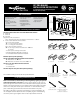
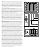
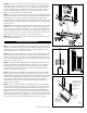
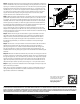

fig. 3
Step 1 Determine the number of railing posts needed for your deck. Post
spacing is 6' or 8' on-center. Example: A 12'x16' deck attached to a building
with a 4' access opening on one side will require a total of eight posts (fig. 1).
Step 2 Install rail posts prior to installing deck boards. Cedar or pressure-
treated pine 4x4 railing posts provide the structural strength for the railing.
The length of each post is determined by the total of the joist width (7-1/4")
+ decking thickness (1") + railing height (36" or 42") + spacing for post cap
(1-1/4") = 45-1/2" or 51-1/2".
Important: Do not notch the 4x4 railing posts. Notching will reduce the
strength of the post and could result in railing collapse or failure (fig. 2a).
Step 3 Position, plumb with a level, and clamp the rail post on the interior face
of the joist. Plumb again. The 4x4 railing post should be bolted to the inside of
the joists using two 1/2"x6" galvanized carriage bolts. Corner posts use a third
carriage bolt inserted through the adjacent joist (fig. 2b).
Step 4 Install decking. Notch deck boards to fit around the 4x4 railing posts.
Allow 1/4" space between the deck boards and any permanent structure or post.
Additional blocking may be necessary on the 4x4 for fastening deck boards.
Step 5 Trim 4x4 post sleeves to length. If you plan to use a post cap, post
sleeves should be a minimum of 1-1/2" longer than the railing height. (fig. 3).
Example: For a 36" high railing, trim post sleeve to a minimum of 37-1/2”, or
longer if desired. Slide a trimmed post sleeve over each 4x4 railing post. Use
shims as needed to create a snug fit. Slide a post base trim over each post
sleeve.
Step 6 Pre-drilled rails. Note: To ensure the outer balusters are equally
spaced, the rail components require trimming at both ends. Ensure the holes
are a minimum of 2-5/16" from post. Using the lower pre-drilled rail as a guide,
place it adjacent to the post sleeves and center the rail so the furthest pre-
drilled holes for the balusters are equal distances from the post sleeves. Mark
the gap between the posts on to the lower rail and trim to fit. (fig. 4)
Step 7 Note: To ensure the balusters are installed plumb, the holes between
the rail sections must all be aligned. Tip: Use a gauge pin or a 3/32" drill bit to
ensure the holes are aligned. Using the trimmed lower rail as a guide, set one
inner rail on the trimmed bottom rail and align the pre-drilled holes. Mark the
cut lines on the inner rail with a pencil. Note: To allow for the thickness of the
brackets, the inner rails should be 1/8" shorter than the outer rails with all holes
equally spaced. Remove an additional 1/16" from the pencil mark on each end
and trim the inner rail to length. Repeat for the second inner rail (fig. 4).
Step 8 Assemble the lower inner rail and support block assembly. A support
block is needed every 2' on-center. Check building codes for a maximum
spacing between deck surface and bottom of rail (sweep). A 3" sweep is
recommended, but can be more or less if codes allow (fig. 3). Trim support blocks
to desired height and pre-drill 1/8" holes in the proper locations. Holes must be
centered on the inner rail for support blocks to fit properly. Using the support
block connectors, fasten support blocks to the underside of the inner rail.
Step 9 Mark the height of the brackets on the inside of the post using the
bracket placement template included in the kit. Another option is to use the
inner rail as a guide. The top of the bracket should be even with the top of the
inner rail assembly. Drill two 1/8" holes through the bracket holes shown on the
template and through the post sleeve for both the upper and lower brackets.
Remove the bracket placement template from the post sleeve and fasten the
upper and lower brackets to the post using two 2" countersunk screws. Tip:
For best results, use a long drill bit or add an extension bit to the drill. Repeat
on the adjacent post. Set the inner rail in between the lower brackets and
predrill a 1/8” hole at each bracket hole and into the inner rail. Fasten the rail
to the brackets using 1" countersunk screws.
fig. 1
fig. 2a
Fig.3.eps
fig. 2b